The movement of a small droplet in the boundary layer of the liquid–vapor flow in a horizontal channel with large velocity gradients is considered. The influence of the Magnus and Saffman lift forces on this droplet and the distance of its separation from the channel wall was investigated. The velocity components of the droplet and its reach distance were determined from the numerical solution of the system of nonlinear differential equations with the use of the Mathcad program.
The Carnot cycle is central to engineering thermodynamics and its teaching. Although on the one hand it is an unattainable ideal, on the other it constitutes a set of concepts to which real heat engine cycles and processes should aspire to and approximate. The Two Property Rule means that cycles may be represented graphically and the principal pairs of properties are p, v (pressure and specific volume) and T,s (temperature and specific entropy). The p, v diagram is truly practical in the sense that it mirrors the indicator diagram, known to generations of past engineering students from engine laboratory experiments. The indicator and its diagram have a venerable history, dating back to 1796 and the very dawn of thermodynamics. The Scotsman James Watt used them to improve engine design to considerable commercial advantage. In 1824, Carnot was unaware of the diagram, most probably because of its extreme commercial sensitivity for Watt. Not until 1834 did Clapeyron make the first use of the p, v diagram to describe the Carnot cycle. The T,s diagram was proposed by the American J (Josiah) Willard Gibbs in 1873 as part of a more general study of how graphical methods could be used in thermodynamics. Gibbs was a mathematical physicist and his thermodynamic contribution was almost a complete inverse to that of Watt. Despite it dating from well after the understanding of the Laws, the T,s diagram and the Carnot cycle are virtually indistinguishable in present-day understanding. So in representing Sadi Carnot’s cycle of 1824 with both p, v and T,s diagrams (which he was unable to do) almost a century of associated thermodynamics history is involved. In this chapter, we study the historical context of these diagrams and their authors. In particular, James Watt was a massive contributor to the industrial revolution and in certain respects a forerunner to Carnot. We use these diagrams to show how the Carnot concept of a perfect heat engine applies across the thermodynamic board, irrespective of working fluid (gas or vapour), of cycle processes (non-flow or steady flow) or of engine concept (work-producer or refrigerator). In addition, the Carnot cycle was the driving force behind the formulation of the Second Law of Thermodynamics and this aspect is reviewed to highlight the contributions of Kelvin himself. We will find that Kelvin has an enduring high reputation here, based on his absolute scale of temperature and his second law statement.
In the paper presented are considerations on the cooperation of the limited capacity heat source with the Organic Rankine Cycle unit. Usually the heat source providing thermal energy to the Organic Rankine Cycle (ORC) may have twofold characteristics. It can be in the form of a single phase fluid, i.e. as hot exhaust gas or hot liquid, or in some cases it may be available as a phase changing fluid, as for example, technological or geothermal steam. Such fluid will be condensed whilst supplying heat to the ORC evaporator. In case of the heat source in the form of a single phase fluid flow its temperature is decreasing in the course of heating of the ORC. In the paper a simple analytical method, based on the energy balance of evaporator, is presented for evaluation of the final temperature of the heat source for ORC installation for two cases, namely single phase fluid and phase changing fluid heat supply. Additionally, the ratio of the heating fluid to the ORC working fluid is presented in function of the minimum temperature difference between the heat source and working fluid.
In the paper the original design of a compact heat exchanger with microjets producing intensification effect is presented. Its primary application is for the domestic Organic Rankine Cycle (ORC), however, the design is universal and may have numerous other applications. The technology of microjets manufacturing is an "in-house" patented design. In the present paper the idea of such a heat exchanger is shown together with the flow and thermal characteristics of the prototype. The developed prototype of heat exchanger is capable of exchanging 5 kW of thermal energy at a logarithmic mean temperature difference (LMTD) of 60 K. The total heat transfer surface equal to 0.0072 m(2) leads to very significant heat fluxes. Measured overall heat transfer coefficient reaches 12000 W/m(2)K, which was calculated using the Wilson method. The description of the Wilson technique used for the determination of the heat transfer coefficient is also presented in the body of the text. That method seems to be, in the authors' opinion, the only one for finding the heat transfer coefficient for such a complex heat exchanger structure. In this case measurements of wall temperatures are not possible and hence the determination of heat transfer coefficient is difficult. The results of performed measurements are satisfactory and encourage for further research of the original design.
W pracy przedstawiono bezwymiarowe kryterium termodynamiczne do selekcji suchych czynnikow roboczych dla organicznego obiegu Rankina, ktore umozliwia wstepną selekcje potencjalnych czynnikow.
Przedstawiono uogolniony model termosyfonu, ktory moze byc rozpatrywany dla szeregu wariantow.Model opiera sie na jednowymiarowych rownanich masy, pedu i energii. Rozpatrzono dwa przypadki termosyfonu, tj. grzanie strony pionowej i chlodzenie strony pionowej oraz drugi, gdzie termosyfon jest ogrzewany na stronie pionowej a chlodzony na poziomej.
The present work aims to provide an explanation to the phenomenon of breakdown of the thin liquid film created by impinging two-phase, liquid–gas jet. Existing in the literature models describe merely the breakdown of single phase liquid films. The model presented here is based on examination of mass and energy equations under the applied criterion of the minimum of total energy. That allows to determine the minimum thickness of isothermal, thin liquid film created by impinging two-phase jet on a solid surface. The mechanical energy of the system consists of kinetic energy of liquid film and surface energy of all physical surfaces consisting for the control surface. An analytical expression for the minimum thickness of such liquid film is derived. The liquid film thickness at the breakdown is a function of the contact angle and shear stresses on the liquid–gas interface. Some comparisons with the experimental data are shown exhibiting a good performance of the postulated model.
Renewable heat sources are rarely suited to the temperature requirements of modern thermal power plants. Thus, our unique opportunity is to deliver to the market power plants optimized for these unused and overlooked thermal resources utilizing Organic Rankine Cycle (ORC). The ORC is similar to the cycle of a conventional steam turbine, except for the fluid that drives the turbine a high molecular mass organic fluid, usually Freon or another low-boiling fluid. This paper analyzes micro combined heat and power plants (micro CHP) operating on ORC, which aims to replace conventional boilers in homes. The heat power of micro CHP is in the range of from ten to a hundred kilowatts, and electric power in the range of from a few to tens of kilowatts. Analysis concerns selection of a cycle, calculation of thermodynamic parameters, and determination of basic dimensions of heat exchangers: condenser and evaporator.
 Dariusz Mikielewicz合作论文数Faculty of Mechanical Engineering, Gdańsk University of Technology19
 h bielinski合作论文数10j a stasiek合作论文数5Jan Wajs合作论文数5S. Gumkowski合作论文数5E. Ihnatowicz合作论文数4M. W. Collins合作论文数4
 J. Stasiek合作论文数4Oktawia Dolna合作论文数2Z. Bilicki合作论文数2m trela合作论文数2E. S̀Liwicki合作论文数2nd micro合作论文数1nano flows conference合作论文数1JR MOSZYNSKI合作论文数1Mw Collins合作论文数1
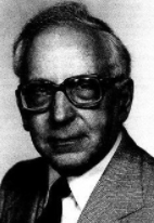 Joseph Kestin合作论文数Brown University1Marian Trela合作论文数1Stanislawa Semiczek-Szulc合作论文数1
 Janusz Madejski合作论文数Politechnika Gdańska1
 Jaroslaw Karwacki合作论文数1
 Robert Matysko合作论文数Institute of Fluid-Flow Machinery, Polish Academyof Sciences1
 Dariusz Butrymowicz合作论文数Institute of Fluid-Flow Machinery, Polish Academy of Sciences1M.W. Collins合作论文数1S. Doerffer合作论文数1B. Sedler合作论文数1
 A. A. Rageb合作论文数1




