In this paper, the equal optical path condition is integrated with a weighted freeform surface superposition algorithm to design the initial layout of off-axis reflective freeform imaging systems. For a single field of view under uniform sampling conditions, the initial layouts of two off-axis four-mirror systems are directly constructed by applying the equal optical path condition in conjunction with an appropriate selection of virtual image points. The results show that, under the single field of view condition, the modulation transfer function (MTF) values of the initial layouts exceed 0.8 at a spatial frequency of 20 line pairs per millimeter (lps/mm). Subsequently, a weighted surface superposition algorithm is employed to superpose freeform surfaces designed for different field points, with optimal weighting factors determined using a simulated annealing algorithm. As a result, the resulting superposed surface maintains relatively high imaging quality across multiple field points, thereby providing a favorable starting point for subsequent optimization. To validate the effectiveness of the proposed method, two initial layouts of off-axis four-mirror systems were designed. Based on these initial designs, the MTF of the first system exceeds 0.6 at a spatial frequency of 20 lps/mm, and the MTF of the second system exceeds 0.8 at a spatial frequency of 20 lps/mm, achieving near diffraction-limited performance.
A micro-electro-mechanical system (MEMS)-based LiDAR beam steering system composed of a cone lens and a metalens is proposed. The cone lens has three key optical surfaces, through which the incoming beam passes and then outputs along the horizontal direction. When the MEMS rotates around the Y axis, the output beam can scan across a 360° field of view in the horizontal direction. Additionally, the output beam can also scan in a vertical field of view (FoV) of 12.3°. The metalens can further reduce the divergence of the output beam in both horizontal and vertical directions. The output beam has a narrow divergence with a divergence angle of 0.313∘×0.287∘. The system provides a design solution for a solid-state LiDAR beam steering system that meets the design requirements of a large FoV with a more miniaturized structure while being easier to integrate and assemble.
Objective LiDARs are crucial sensors widely applied in terrain exploration, species detection, autonomous driving, and numerous other fields. Its core technology mainly consists of three aspects: ranging, steering, and imaging. At present, the all-solid-state LiDAR without any mechanical moving parts is a hot research area with significant application value. However, the two main types of all-solid-state LiDAR, namely the optical switch-based LiDAR and the optical phased array (OPA) LiDAR, face the problem of limited scanning angles. Therefore, the design of a LiDAR beam steering system incorporating a new optical system holds broad application prospects. The large field-of-view scanning achieved with conventional optical systems still faces the problem that the beam is dispersed in one direction, and it is difficult to maintain collimation simultaneously in the horizontal and vertical directions. To solve this problem, we propose an optical switch-based LiDAR beam steering system that includes both a metalens and a cone lens. The results show that the system can achieve the designed horizontal field of view of 360 degrees and a vertical field of view of 8 degrees while maintaining a beam divergence angle of approximately 0.018 degrees in both the horizontal and vertical directions. Methods Our designed beam steering system of an optical switch-based LiDAR consists of three main components: the photonics integrated circuits, the metalens, and the cone lens. In the design of the photonic integrated circuits, we simulate and analyze a single grating coupler using the finite difference time domain (FDTD) method. The divergence angles of the emitted beam in the X and Y directions for a single coupler are 11.1 degrees and 10.9 degrees , respectively. For the metalens, we first conduct simulations of each cell and construct the overall model of the metalens through calculations. We then analyze it by comparing the desired target phase distribution with the phase distribution achieved by the constructed metalens. The cone lens has conical upper and lower surfaces, which is scaled to meet the requirement for total internal reflection on the s2 surface in our design. It serves as a macroscopic optical element that can be fabricated through single-point diamond machining or molding techniques, highlighting the high feasibility of our design. In this design, the key factor we consider is to expand the vertical field of view while maintaining the horizontal field of view of 360 degrees. In some conventional systems, it is difficult to ensure collimation and narrow beam divergence in both horizontal and vertical directions, and some even use mechanical moving parts to achieve this. According to the characteristics of the optical switch-based LiDAR, we perform beam steering separately for each vertical field of view. Due to the different effects of the metalens, the beams are in total reflection at different positions on the inner surface of the cone lens and are collimated after emission. We well design the overall model in the article to solve this problem. On this basis, we analyze the optical system and obtain results such as the system design schematic and spot diagram, and view the irradiance distribution and luminous intensity distribution curves. We demonstrate the patterns of beam steering by switching between different sections of the grating couplers at four different positions. Results and Discussions We design an optical switch-based LiDAR beam steering system that contains photonic integrated circuits, a metalens, and a cone lens. The photonic integrated circuits consist of an array of optical switches and grating couplers, which are arranged in the form of eight ring arrays, and beam steering is achieved by switching between the grating couplers at different positions. In the study, we design each module separately and combine them for overall analysis, thus confirming the results of our design and demonstrating the possibilities of real applications. By applying our designed system, the horizontal field of view can be expanded to 360 degrees while maintaining an 8 degrees field of view in the vertical direction. The resolution of the system is 0.7 degrees in the horizontal direction and 8 degrees in the vertical direction. The results show that the system has a narrow beam divergence angle of 0.018 degrees x 0.018 degrees. Conclusions We propose and design a beam steering system for optical switch-based LiDAR. Its core advantage is the ability to achieve a 360 degrees horizontal range and an 8 degrees vertical field of view compared to conventional LiDAR optical scanning systems. The system demonstrates strong application potential by utilizing the smallest possible components and a compact structure to achieve high resolution and narrow beam divergence in both the horizontal and vertical directions. In the future, we will further focus on the design of the photonic chips, and expanding the array scale will contribute to widening the field of view in the vertical direction.
In this study, we have designed freeform mirrors capable of transforming uniform irradiance distribution into complicated irradiance distribution. The design methodology incorporates two key algorithms: Poisson-based grid optimization and a discrete cosine transform (DCT). The grids on the target plane were optimized using Poissonbased grid optimization while maintaining uniformity on the incident plane. By obtaining grids for both input and target planes, we derived the normal vector field and utilized the DCT to calculate the sags of the freeform surface. Several examples have been devised to substantiate the validity of the approach. For Case 1 and Case 2, the results demonstrate that these freeform surfaces produce high-contrast and complicated irradiance maps with a notable proportion exceeding 4:1 in terms of irradiation intensity ratio between the graphic area and the background. In Case 2, when compared to the prescribed irradiance distribution, the normalized cross correlation values for generated irradiance distributions by the freeform mirror, both with and without sag error, are 94% and 96%, respectively. Furthermore, Cases 3 and 4 demonstrate that incident beams with complex irradiance distributions can be transformed into uniform irradiance profiles by the freeform mirror designed using the proposed method, achieving uniformity levels of 93% and 95%, respectively. It is noteworthy that the incident beam aperture in Case 4 exhibits an elliptical shape. (c) 2024 Optica Publishing Group. All rights, including for text and data mining (TDM), Artificial Intelligence (AI) training, and similar technologies, are reserved.
Objective LiDAR plays a crucial role in vehicle- assisted and autonomous driving by detecting the surrounding environment and aiding in obstacle avoidance. Micro-electro-mechanical system (MEMS)- based LiDARs offer rapid scanning speed, high resolution, and cost-effectiveness, which makes them widely used commercially. A MEMS-based LiDAR with a 360 degrees field of view can comprehensively scan the scene around a vehicle, which offers significant practical value. However, conventional optical systems struggle to achieve consistent outgoing beam divergence angles in both horizontal and vertical directions due to their asymmetric fields of view when attempting 360 degrees scanning. To tackle this challenge, we present a panoramic LiDAR optical system based on MEMS scanning. It enables 360 degrees horizontal scanning of the environment using a torus lens, anamorphic prism, and MEMS mirror. Simulation results demonstrate that our design maintains outgoing beam divergence angles at approximately 0.32 degrees horizontally and 0.13 degrees vertically across different MEMS placement configurations. Methods The MEMS-based scanning LiDAR system comprises two modules: the transmitting module and the receiving module. The transmitting module includes laser LA, anamorphic prism P1, MEMS, and torus lens L, while the receiving module consists of anamorphic prism P2 and detector D. In the transmitting module, the laser beam emitted by LA undergoes refraction through the special spherical surface S1 on top of anamorphic prism P1. This beam converges after passing through surface S1 and then enters MEMS through the lower surface S2 of anamorphic prism P1. After reflection by MEMS, the beam passes through region A of prism P1 where total internal reflection occurs. The beam then moves into region B where it undergoes refraction before being output. The beam exiting region B is further collimated by toroidal lens L and finally output with a small divergence angle in the horizontal direction. By rotating the MEMS mirror 360 degrees around the Z-axis, the LiDAR achieves a scanning field of view of 360 degrees. The emitted beam strikes an obstacle object, causing diffuse reflection on its surface which scatters light in random directions. Only scattered beams with direction angles closely matching the output beam can enter refraction region B of prism P2. The beams entering region B are redirected towards total reflection region A in prism P2. The reflected beams from region A of prism P2 pass through the bottom surface S2 of prism P2 and ultimately converge onto detector D. Several crucial considerations must be taken into account for the design of anamorphic prism P1. It is imperative to achieve total internal reflection within region A, which enables ray reflection and manipulation without relying on high anti- reflection film coatings. This necessitates precise control over the angle between the total reflecting surface A and the vertical direction. Another point to note is that surface S1 of anamorphic prism P1 should have a certain converging effect on the beam, but not collimation. The curvature of surfaces A and B in anamorphic prism P1 differs in the horizontal and vertical directions, which leads to a marked difference in divergence angle between the horizontal and vertical directions as the beam passes through these surfaces. In the design and optimization process, the priority is to ensure good collimation in the horizontal direction. Therefore, a torus lens L is added outside anamorphic prism P1. The torus lens has minimal effect on horizontal divergence but significantly improves vertical collimation. The design concept of anamorphic prism P2 is similar to anamorphic prism P1. Results and Discussions The design of a panoramic LiDAR optical system based on MEMS scanning enables 360 degrees horizontal scanning of the surrounding environment. Moreover, the vertical field of view can be extended up to 6.7 degrees. An anamorphic prism effectively reduces the divergence angle of the output beam to 0.32 degrees horizontally. After passing through the torus lens, it reduces the vertical divergence angle to 0.13 degrees . Simulation results demonstrate that consistent outgoing beam divergence angles of approximately 0.32 degrees horizontally and 0.13 degrees vertically are maintained across different MEMS positions within this system configuration. Transmitting and receiving modules are positioned on either side of the MEMS. Calculation results indicate a maximum detection distance of approximately 200 m. Furthermore, calculations reveal that the ambient light noise reflected by the environment is approximately 0.01 times lower in intensity compared to the useful signal light. Conclusions We design a MEMS-based LiDAR system capable of achieving 360 degrees horizontal field of view ring scanning. The system comprises a transmitting module and a receiving module positioned on opposite sides of the MEMS device. The receiving module comprises a specially- shaped prism P2 and a detector D. The top surface of prism P2 is aligned in the same plane as the special- shaped prism P1 of the transmitting module, which maintains a consistent structure throughout. The system achieves high resolution in both horizontal (0.32 degrees) and vertical (0.13 degrees) directions, utilizing minimal components and featuring a compact structure. Moreover, the optical components are symmetrically oriented, which results in manageable processing complexity and immense commercial potential for this system. Future research will focus on analyzing the influence of manufacturing tolerances and equipment variations on resolution.
Objective The vertical-cavity surface-emitting laser (VCSEL) is a typical semiconductor laser widely employed in high-speed optical communication, optical sensors, pumped solid-state lasers or fiber lasers, LiDAR, and structured light applications. The irradiance distributions of the VCSELs typically conform to a Gaussian distribution. In various application scenarios such as laser processing and laser illumination, it is necessary to achieve a uniform irradiance distribution on the target plane. Among various methods for laser shaping, freeform optical components have gained increasing popularity due to their high optical efficiency and flexibility in controlling light distribution. However, there is a paucity of literature regarding the utilization of freeform optical elements for shaping VCSEL lasers, particularly in terms of designing freeform surfaces to manipulate irradiance distribution for VCSEL array modules. In this paper, we present the design of both a freeform lens and a freeform lens array specifically and tailor the light distributions for single VCSEL sources and VCSEL arrays respectively to achieve a uniform irradiance distribution on the target plane. Methods The design of a freeform shaping lens for VCSELs aims to achieve a uniform irradiance distribution on the target surface for the output beam. The front surface of the lens is aspherical, while the back surface is freeform. The rays emitted by the VCSEL are collimated through the aspherical surface, and the collimated beam is then incident on the freeform surface, through which the irradiance distribution is regulated to produce a uniform irradiance distribution on the target plane. During the design process, a virtual surface is incorporated within the middle region of the freeform lens to establish a relationship between its energy distribution and that of the target plane. This enables the determination of direction vectors of incident and outgoing rays, as well as obtaining normal vectors for each point on the sample points of the free-form surface. By formulating a Poisson equation relating sag of freeform surface and normal vector, we employ the discrete cosine transform method to solve it and obtain vector heights for achieving the desired performance. Due to the size of the VCSEL source, the rays emitted by the VCSEL still have a small divergence angle after passing through the aspherical collimation. The effect of the divergence angle on the uniformity of the irradiation distribution on the target surface is investigated. It is shown that the uniformity is reduced to 85% when the residual divergence angle reaches 3 degrees. A VCSEL array consists of several individual VCSEL modules equipped with a freeform lens. An evaluation function is constructed that guarantees simultaneous control of the uniformity and efficiency of the irradiance distribution of the VCSEL module array. The optimal spacing between these modules is obtained using the evaluation function by employing the Antlion optimization algorithm. The optimal VCSEL array enables the generation of a uniform irradiance distribution on the target plane with high optical efficiency. Results and Discussions A freeform lens is specifically designed for a single VCSEL light source, featuring an aspherical front surface and a freeform back surface. The emitted beam from the VCSEL light source, with a waist of 0.1 mm and a divergence angle of 8 degrees, is efficiently transformed into a square uniform spot of 10 mmx10 mm on the target plane, achieving an impressive irradiation uniformity of 93.9%. The second freeform lens is specifically designed for a VCSEL source with an emitting area of 1 mmx1 mm; however, it only achieves an irradiation uniformity of 53.5% on the target plane. Each VCSEL combined with the second freeform lens forms what we refer to as a VCSEL module. The optimal 3x3 array of modules is generated by employing the antlion optimization algorithm to determine the optimal spacing between VCSEL modules. With the implementation of an optimized VCSEL module array, we have successfully achieved a remarkable enhancement in irradiation uniformity, reaching up to 85.2% on the larger target plane of 30 mmx30 mm. Moreover, our study has demonstrated an impressive overall light efficiency level of 91.8% for the VCSEL array. Conclusions The relationship between the sags of the freeform surface and the normal vector of each sampling point is transformed into a Poisson equation in this paper, and the sags of the freeform surface are obtained using the discrete cosine transform (DCT) method. By employing this approach, a freeform lens can be designed to achieve uniform irradiance distribution on the target plane with a high level of uniformity reaching 93.9%. Furthermore, we address an optimization problem for VCSEL arrays by transforming it into an intensity homogenization problem through multiple image superposition. The analysis reveals that to achieve uniform irradiation distribution from VCSEL arrays, it is necessary to generate non-uniform irradiance distribution on edge regions by individual VCSEL modules. Based on nine VCSEL modules with the optimal spacing, we can achieve uniform irradiance distribution on the target plane with a uniformity of 85.2% and an optical efficiency of 91.8%. The forthcoming research will explore the impact of fabrication and assembly tolerances of the freeform lenses on irradiation uniformity.
Adaptive optics is widely used to correct aberrations in the human eye, achieving high-resolution imaging of fundus cells and microvessels. Traditional adaptive optics systems are limited by the dynamic range of the Shack Hartmann wavefront detector and are only suitable for some people, and cannot perform fundus high-resolution imaging in people with high refractive errors. In order to improve the universality of fundus adaptive optical imaging system, this paper designs a high-resolution fundus adaptive optical imaging system based on voice coil deformation mirror. The introduction of the Badal focusing system can perform high-resolution imaging of the fundus with the diopter of the human eye between -8 similar to 8 D. In this system, the traditional annular diaphragm is replaced with an adjustable axial cone lens set, the spacing of positive and negative axonal cone lenses are controlled to adjust the inner diameter of annular light in order to adapt the cornea of different eyes, and avoid stray light reflected by the cornea. Large field of view imaging is realized through visual beacon guidance. The simulation results show that the illumination subsystem has a uniform distribution of retinal illumination in the fundus. Within the set tolerance, at least 90% of the MTF values reach 0. 21 at 25 lp/mm (corresponding to 4 mu m on the retina). The corresponding optical path was built in the laboratory, and the simulated human eye with large distortion was imaged, and a good imaging effect was obtained.
Objective Diffractive optical elements (DOEs) are widely applied in light distribution control such as laser beam shaping, structured light illumination, and beam splitter. Various methods can be utilized to design DOEs, such as Gerchberg-Saxton (GS) algorithm, simulated annealing algorithm (SAA), and Genetic algorithm (GA). These traditional methods can design DOE effectively for a group of initial parameters, such as beam waist radius, wavelength, size of target plane, and distance between DOE and target plane. However, when any parameter is changed, the new phase profile needs to be recalculated, which is time-consuming, especially by global optimization algorithms such as SAA and GA. To overcome the disadvantages, this paper employs a machine learning algorithm to design the DOEs with continuous phase distribution. The mapping relationship of system parameters such as waist radius, size of target plane, and distance between DOE and target plane with DOE phase coefficients is constructed by the neural network. With this relationship, the DOE phase coefficients can be predicted automatically when a set of system parameters are given. It overcomes the limitation of the traditional design methods which need to recalculate the phase distribution when the parameters are changed. Methods Machine learning algorithm is employed to design the DOE with continuous phase distribution, which can be used for laser shaping. Firstly, the gird energy mapping method is applied to calculate the phase distribution data of the DOEs with a set of initial parameters including waist radius, size of target plane, and distance between DOE and target plane. The DOE enables the laser to generate uniform laser irradiance distribution. Secondly, the phase distribution data of DOE elements are fitted into a polynomial. Then 10000 sets of initial parameters are generated. With the 10000 sets of initial parameters, the phase distribution data of 10000 sets of DOEs are calculated by grid energy mapping. The initial parameters of the DOE and DOE phase coefficients are taken as input and output data to train the neural network, respectively. The trained network constructs a mapping relationship between system parameters and phase coefficients. With this relationship, the DOE phase coefficients can be predicted automatically when a set of system parameters are given. Results and Discussions Several important results are obtained as follows. 1) Within the pre-trained range, the trained BP neural network is applied to predict the corresponding DOE phase coefficients. The randomly selected 20 sets of DOE system coefficients are taken as the test samples. The prediction accuracies of the DOE phase coefficients are all above 99. 9% (Fig. 6). The uniformity of the laser irradiance generated by the 4 sets of DOEs which are designed by machine learning and energy mapping method respectively is almost the same (Fig. 7 and Fig. 8). 2) The influences of system parameters on the prediction accuracy are studied while the system parameters are beyond the training range. Also, the influence of each parameter on the prediction accuracy is analyzed. When all the parameters are expanded by 80% and 55% based on the pre-trained range, the accuracy of prediction is above 99. 5% and 97. 5%, respectively (Fig. 10). It is shown that the size of the target plane has the most obvious influence on the prediction accuracy when the size of the target plane is smaller than the predetermined size (Fig. 11). Conclusions The machine learning algorithm is employed to design DOEs with continuous phase distribution. The parameters of the DOE and DOE phase coefficients are acquired automatically as input and output data respectively to train the neural network. The trained network constructs a mapping relationship between system parameters and phase coefficients. With the relationship, the DOE phase coefficients can be predicted automatically when a set of system parameters are given. The results show that the prediction accuracy of the phase coefficient is above 99. 9% within the trained range of the system parameters. When all parameters are expanded by 80% and 55% in both forward and reverse directions based on the pre-trained range, the prediction accuracy remains above 99. 5% and 97. 5%, respectively. It is also shown that the size of the target plane has the most obvious influence on the prediction accuracy when the size of the target plane is smaller than the predetermined size. In future work, the method may be extended to design the DOE with discontinuous phase distribution.
Objective The laser beam shaping technique is widely used in laser processing, welding, display, lighting, and other applications. The freeform surface is extensively applied in laser beam shaping because of its high design freedom, accurate control of light distribution, and high transmittance. It is known that a freeform surface with good smoothness is easier to be manufactured. Therefore, it is crucial to design a freeform lens with good smoothness. In the paper, a design method of lenses with good-smoothness freeform surfaces is presented. The optimal mesh distribution on the target plane is generated by the Poisson mesh optimization algorithm. With the optimal mesh distribution on the target plane, the normal vector at each sampling point on the free surface is calculated according to the energy mapping between input beam and output beam. The sag of the freeform surface can be obtained by solving Poisson equation established by the normal vectors and sags at sampling points. Finally, the freeform lens with good smoothness is designed. With the freeform lens, the laser beam with a circular aperture can be shaped into a rectangular spot on the target surface with uniform irradiance distribution. Methods Firstly, the initial meshes on the cross-section of the incident beam and the target plane are generated. The mesh distribution on the target plane is optimized by the Poisson mesh optimization algorithm, in which an error function is employed to reflect the energy distribution error between mesh on the incident section and expected energy distribution of the corresponding target surface mesh. The partial differential equation (PDE) of the error function and the pressure field is constructed by the idea of fluid mechanics. Then, the finite difference method is employed to solve the PDE so as to calculate the distribution of the pressure field. After the gradient of the pressure field is calculated, a displacement vector field can be obtained, which determines the direction and magnitude of movement of every vertex in the target plane mesh. By the method, the optimal mesh distribution on the target plane can be obtained. Given the optimal distribution, the normal vector at each sampling point on the freeform surface can be calculated according to the mapping relationship between incident and outgoing rays. The sag of the freeform surface can be obtained by the solution to Poisson equation established by the normal vectors and sags at sampling points. Finally, the assembly tolerances of the freeform lens are analyzed by a random statistical analysis method. Results and Discussions Two freeform lenses are designed to transform the circular laser beam with Gaussian irradiance distribution to that with uniform irradiance distribution on square and rectangular target planes with uniformity of 91% and 93% (Fig. 7), respectively. The size of the two target planes is 30 mmx30 mm and 60 mmx40 mm, respectively. To verify the smoothness of the freeform surface, a polynomial is used for fitting, which has nine terms, and the highest order is six. The RMSE after fitting is about 1. 394x10(-3) (Figs. 8 and 9). The uniformity of the target plane remains almost unchanged when the freeform lens is constructed with the fitted data points. It is shown that the freeform surface designed by the method presented in the paper has good continuity and smoothness. Finally, the assembly tolerances of the freeform lens are analyzed by a random statistical analysis method. The results show that within the given tolerance range, the change in uniformity is less than 6%, and the uniformity can be maintained at about 88% for most of the samples (Figs. 10 and 11). Only about 1% of the samples report a decrease in uniformity by more than 10%. Conclusions In this paper, a freeform lens design method for laser beam shaping is proposed, which has two key steps, Poisson mesh optimization and freeform surface construction by the solution to Poisson equation. The Poisson mesh optimization algorithm is mainly used to optimize the mesh distribution on the target plane so that the light distribution on the target plane meets the expected distribution. After four iterations, the optimal mesh distribution is achieved on the target plane. Given the optimal mesh distribution on the target plane, the normal vector at each sampling point on the free surface is calculated according to the energy mapping between input beam and output beam. The sag of the freeform surface can be obtained by the solution to Poisson equation established by the normal vectors and sags at the sample points. In this way, the freeform lens is designed. To verify the feasibility of the method, this study designs two freeform lenses to transform the circular laser beam with Gaussian irradiance distribution to that with uniform irradiance distribution on square and rectangular target planes, with uniformity of 91% and 93%, respectively. A polynomial is used for fitting to verify the smoothness of the freeform surface, which has nine terms, and the highest order is six. The RMSE after fitting is about 1. 394x10(-3). The uniformity of the target plane remains almost unchanged when the freeform lens is constructed with the fitted data points. Finally, the assembly tolerances of the freeform lens are analyzed by a random statistical analysis method. The results show that the uniformity of most of the samples is higher than 88% within the given tolerance range. The design is of good practical application value.
Given a cubic space, it is easy to uniformly illuminate the floor with light sources placed on top. However, little has been reported about uniform illumination on walls with the same configuration of light sources. Here we present a luminaire consisting of nine light-emitting diodes (LEDs) with perfect Lambertian distribution, placed on the top as a 3 x 3 rectangular LED array. The distances between LEDs and tilt angles of each individual LED are adjustable and optimized by an annealing algorithm. After optimization, the array produces a rectangular illumination pattern on one wall with a uniformity of about 89%. Analysis shows that the tilt angles of individual LEDs are key parameters for uniform side illumination. In a scenario that is more practical, the tilt angles of all the LEDs are set to be the same, only decreasing the uniformity to 83%.
A method that can be applied to two-dimensional surface shape weighted superposition is proposed, which can control the light distribution by designing free-form surfaces for extended LED light sources. Five sampling points are taken on the light source surface, which are used as five point light sources to generate five free-form surfaces, and each free-form surface data point is multiplied by a weight factor. The weighted free-form surfaces are superimposed, and the superimposed free-form surfaces are used as the initial outline. The particle swarm algorithm is used to further optimize the weight factor to obtain the optimal weight factor, and the five freeform surfaces are weighted and superposed using the optimal weight factor. The light distribution of the extended LED light source is adjusted by using the superimposed optimal free-form surface lens. The simulation result shows that this method enables the uniformity of the illuminance of the target surface to reach 75%, which is 15% higher than that generated by the initial lens on the target surface. This method has the advantages of fewer optimization variables, good surface continuity, and fast convergence speed.
Off-axis reflective afocal optical systems have important applications in space telescopes. Freeform surfaces can correct the asymmetric aberrations in off-axis reflective afocal systems. It is very important to design the initial layouts of freeform off-axis reflective afocal systems. In this paper, an orthogonal seed curve extension (OSCE) algorithm was proposed to design the initial layouts of freeform off-axis reflective afocal systems directly. Off-axis afocal three-mirror and four-mirror systems with magnifications of 10 and 20, respectively, were designed to verify the feasibility of the method. The results show that the root-mean-square (RMS) wavefront error of the initial layout of the off-axis three-mirror system is 0.36 lambda and that of the off-axis four-mirror system is 0.18 lambda The RMS wavefront errors of the two initial layouts after optimization are both less than 0.02 lambda.
A double seed curve extension (DSCE) method is proposed to design a freeform surface directly in an off-axis reflective imaging system. Compared with the basic seed curve extension (SCE) method, the DSCE can effectively reduce the error of freeform surface construction and improve the imaging quality of the off-axis reflective imaging system. In addition, the method can be employed to design an off-axis reflective imaging system consisting of multiple freeform surfaces with several virtual image points set in advance. In order to verify the DSCE method, three examples are given. One is the off-axis freeform one-mirror system, one is a compact off-axis three-mirror imaging system with two freeform surfaces, and the other is an off-axis reflective system with three freeform surfaces. The modulation transfer function (MTF) of the one-mirror system is greater than 0.9 at 20 lp/mm, which is close to the diffraction limit. The average of the sagittal and tangential MTFs of the second system designed by the SCE and DSCE methods are 0.26 and 0.74 at spatial frequency of 20 lp/mm, respectively. And the MTF of the last system designed by the DSCE method is greater than 0.9 at 20 lp/mm, which is better than that of the SCE method.
影响大口径地基自适应光学望远镜成像的因素很多,为获得近衍射极限的高分辨力成像效果,需要对系统的关键参数进行优化.本文分析了影响地基光学望远镜成像的误差源,建立合理的误差评价模型.并利用仿真的方法对该模型进行了验证,并对湍流条件、望远镜口径、采样频率、变形镜驱动器间距、导星等关键参数进行了优化分析.与仿真结果对比表明:误差模型预测精度在较好的观测条件下能达到30 nm以内.该模型也为自适应光学系统在生物显微成像、眼底成像、激光大气通信等领域的应用提供了参考.
In this paper, an off-axis two-mirror system that can not only make the output beam irradiance distribution uniform, but also control the output beam wave-front and beam-expansion ratio, is designed for laser shaping. By setting two constraints and initial conditions, the iterative relationship between the adjacent sampling points on the free surface can be obtained, and all the sampling points on the whole free surface can be calculated. We use a software to verify the system, and the 16 mm X 16 mm square aperture is transformed into an 80 mm X 80 mm square aperture and a 120 mm X 20 mm rectangular aperture; the outgoing beams arc all collimated beams. The results show that the square spot uniformity is 90. 71 %, and the beam expansion ratio is 5; the rectangular aperture spot uniformity is 91.75%, and the beam expansion ratios in the horizontal and vertical directions arc 7.5 and 1.25, respectively.
Voice coil actuator (VCA) has the merits of no hysteresis, fast response and large stroke. It has been used in the secondary mirror of large optical telescopes. To improve its efficiency, a high efficiency moving magnetic voice coil actuator was designed. And a three-dimensional model of VCA has been built and analyzed with finite element analysis software to simulate its magnet magnetizing direction, magnet size, coil size and structure contributed to a more accurate result of the electromagnetic force and efficiency. In order to generate large electromagnetic force and high efficiency, the above parameters are simulated and optimized respectively. The result shows that the output force of the small caliber moving magnetic VCA is up to 0.43 N and the actuator constant is up to 0.9. There is a good linear relationship between the output force and the input current, which provides a theoretical basis for the development of the VCA for next generation deformable mirror.
A freeform optical system of automotive Head-Up Display (HUD) was designed. In the initial layout design of the HUD optical system, the sample points on two optical freeform surfaces of the HUD optical system are calculated by the seed curve extension algorithm. And the two freeform surfaces are expressed by the extended polynomials. Then the ray tracing is performed for the initial layout of the HUD optical system at center field of view with 0.5 mm ray sampling interval. The results show that the performance of the initial layout of the HUD optical system is the diffraction-limited, which can be used as the starting point for further optimization at full field of view. After optimization, the final HUD optical system is obtained. In order to simulate the observation of human eyes, several test points in the Eyebox are taken as object points, which are imaged on the image plane by the HUD optical system. The modulation transfer function plots of the several test points are greater than 0.5 at 6 lp/mm, which are close to diffraction limit. And the distortions of the final HUD system are less than 2%. Finally, the manufacture tolerances of two optical freeform surfaces are analyzed. The results show that the modulation transfer function plots of the HUD optical system are higher than 0.3 with the tolerance PV values of 0.42 mu m and 0.62 mu m of the two optical freeform surfaces respectively. For the current
The structure of 7 actuators VDM is designed, and the mechanical characteristics of its mirror are analyzed based on the finite element method with ANSYS software. The maximum deformation and stress of the VDM under different material and physical parameters are simulated and discussed. The results show that the designed VDM has an outstanding comprehensive performance, and basically meets the requirements of applications. Our simulation results can provide a reasonable reference for the application of VDM.
In this paper, a method of how to construct a freeform surface directly in an off-axis reflective image system is proposed. The method includes both the seed curve extension algorithm and simulated annealing algorithm. Firstly, the sample points on the unkown freeform surface were be obtained quickly by the seed curve extension algorithm. Then the continuity of the freeform surface is evaluated by calculating the angle between the normal vectors at the adjacent sample points. At last the freeform surface was fitted to an extended polynomials using simulated annealing algorithm. The method is employed to construct a freeform surface directly which is used as a primary mirror in an initial layout of an off-axis two-mirror system.
为了实现蓝宝石基底上双截止透可见区的特性(截止带波长为0.3~0.4μm、0.8~1.1μm,通带波长为0.4~0.8μm),初始结构采用双截止膜系,可截止近紫外和近红外,在蓝宝石基底的一侧实现可见光高透的宽通带滤光片,选用TiO2和SiO2分别作为薄膜高、低折射率材料,来实现双波段截止的目的,薄膜的设计层数为42层,总厚度是3.6μm,采用电子束蒸发物理气相沉积法来实现镀制,并通过分光光度计测试镀制样品的透射率,测试结果显示截止区(0.3~0.385μm和0.824~1.1μm),平均截止深度分别达到了0.029%和0.127%,通带0.405~0.788μm波段的平均透过率达到97.68%,通带半宽度HFWD为398 nm(402~800 nm),有效地抑制了"半波孔"现象出现,并具有双波段截止和高通带透过率的特点.在环境测试中:薄膜的稳定性良好,膜层间匹配度适宜.因此,该双波段截止透可见滤光片可用于某些极端的环境条件中.
 Lifa Hu (胡立发)合作论文数School of Science, Jiangnan University13
 Huaxin Zhu (朱华新)合作论文数School of Science, Jiangnan University12
 Qihong Lou (楼祺洪)合作论文数Shanghai Institute of Optics and Fine Mechanics, Chinese Academy of Sciences9
 Jun Zhou (周军)合作论文数Shanghai Institute of Optics and Fine Mechanics, Chinese Academy of Sciences;University of Chinese Academy of Sciences8
 ChaoWei Zhu (朱焯炜)合作论文数6Lizhi Que (阙立志)合作论文数6Jingxing Dong合作论文数6Liu Xin-Yu合作论文数5Wen Shen (申文)合作论文数5
 Yixin Zhang (张逸新)合作论文数School of Science, Jiangnan University5Wenchao Ma (马文超)合作论文数5Yunrong Wei合作论文数5Hongxiang Pan合作论文数4Yangliu Zhang合作论文数4Cao Shuo合作论文数4Wen-yu ZHANG (张文裕)合作论文数4Dong-ting HU (胡栋挺)合作论文数4Xiu-mei ZHANG (张秀梅)合作论文数4
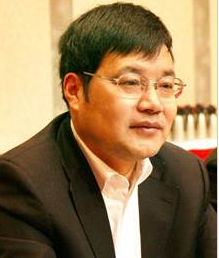 Zhicheng Ji (纪志成)合作论文数School of Internet of Things Engineering, Jiangnan University4
 Shumei Gao (高淑梅)合作论文数School of Science, Jiangnan University4
 Jingjing Wu (吴晶晶)合作论文数School of Science, Jiangnan University4Zhuowei Zhu (朱焯炜)合作论文数4Jing-hui CAO (曹晶辉)合作论文数3Chen Xingtao合作论文数3
 Li Xuan (宣丽)合作论文数University of Chinese Academy of Sciences;Changchun Institute of Optics, Fine Mechanics and Physics, Chinese Academy of Sciences3Zi-yun ZHAO (赵子云)合作论文数3
 Guoqing Chen (陈国庆)合作论文数School of Science, Jiangnan University3
 Cheng Liu (刘诚)合作论文数School of Science, Jiangnan University3
 Weiying Qian (钱维莹)合作论文数School of Science, Jiangnan University3Xinghai Lu合作论文数3
 Chao Liu合作论文数2
 Zhaoliang Cao (曹召良)合作论文数University of Chinese Academy of Sciences;Changchun Institute of Optics, Fine Mechanics and Physics, Chinese Academy of Sciences2Shao Jiaqiang (邵加强)合作论文数2Chen Guo-qing合作论文数2Hu GU (顾虎)合作论文数2Li Xiao合作论文数2
 Xia Liu (刘霞)合作论文数School of Chemistry, Southwest Jiaotong University2
 Quanquan Mu (穆全全)合作论文数Changchun Institute of Optics, Fine Mechanics and Physics, Chinese Academy of Sciences2
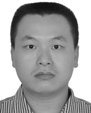 Yifeng Huang合作论文数Shanghai Jiao Tong University, Shanghai Jiaotong Univ.2Zhijun Yuan (袁志军)合作论文数2Yanli Zhao (赵艳莉)合作论文数2Ying Hu (胡莹)合作论文数2Dayu Li (李大禹)合作论文数2Xu Wang合作论文数2Wei Wang合作论文数2Pan-ling LEI (雷盼灵)合作论文数1Wei Bai-lin合作论文数1Chaoyi Qian合作论文数1Gao Pei-li合作论文数1




