In order to reduce the costs of integration and verification processes and to optimize the assembly, integration and verification (AIV) flow in the prototype development of small- and medium-sized spacecrafts, an industrial six-axis robot was used as a universal mechanical ground support equipment instead of a tailored prototype specific ground support equipment (GSE). In particular, a robotic platform offers the possibility of embedding verification steps such as mass property determination into the integration process while offering a wider range of ergonomic adaption due to the enhanced number of degrees of freedom compared to a classical static Mechanical GSE (MGSE). This reduces development costs for projects and enhances the flexibility and ergonomics of primarily mechanical AIV operations. In this paper, the robotic MGSE system is described, the operational prospects for in-line verification are elaborated and an example is given showing the possibilities and challenges of its operational use as well as its in-line mass determination capabilities. For this purpose, a method has been developed that allows for the precise measurement of the spacecraft mass using the robot’s existing technology without the need for additional hardware. Subsequent work will extend this to determine the center of gravity and the moments of inertia of the payload on the robotic MGSE.
A design for a 4 m long, ultra-light, high-gain, helical Antenna made from fiber-composite material will be presented. The antenna was designed for the DLR NanoSatellite Mission AISat to receive signals from the Automatic Identification System (AIS) of maritime applications. A description of the antenna deployment strategy including release mechanisms will be given. The proof of concept will be presented based on experimental results gained during the 15. DLR parabolic flight campaign (PFC) in March 2010 and several development tests. Finally, in-orbit demonstration was performed during the two years of operation of the AISat after the successful launch on June 30, 2014 from Sriharikota (India). The AISat satellite was developed at the DLR Institute of Space Systems aiming at the worldwide receiving of AIS signals. These signals can usually be received along coast lines or from ship to ship in range of sight. They provide identity, position, velocity and heading and are therefore used for ship tracking. A number of AIS satellites already exist but especially in areas with high ship traffic density identification problems arose due to the high signal density. Therefore AISat has a distinctive ultra-light, high-gain, helical antenna which allows to focus on comparably small areas on the Earth surface. IT thus shall enable the receiving of Class A and B and SART signals especially in high traffic density zones. The antenna is a 4 m long and 0.57 m in diameter deployable helix antenna made from fiber composite material, which can be stowed in a very flat volume of merely 100 mm height. The wire of the antenna is made from carbon fiber material with a diameter of 8 mm. It is covered with a copper cord for high electrical conductivity. Based on its design with 8 windings the total length of the wire itself is approx. 16 m. Through the dedicated usage of fiber composite materials this wire weighs less than 1 kg including the copper cord. In stowed configuration, in which it is held down by 3 release mechanisms, the antenna has stored elastic energy like in a spiral spring. After release the structure deploys autonomously in orbit to a length of 4 m. When deployed, the antenna is still pre-stressed using control cords in order to increase its bending stiffness.
In the recent past, an increasing interest has been devoted to the possibility of receiving Automatic Identification System (AIS) messages via Low Earth Orbit (LEO) satellites. While the principle has been demonstrated to be a viable option for monitoring vessel traffic over oceans and vaste land areas, the achievable performance from a communications viewpoint is far from optimal. Recently, it was shown how AIS traffic seen at a satellite can be very accurately modeled resorting to simple random access schemes. Leveraging this result, in this work we propose a simple yet flexible analytical framework capable of predicting channel load and overall reception performance taking into account the spatial distribution of vessels as well as their traffic generation pattern. Feeding the model with ship speed and location data derived from experimental settings, we discuss the achievable efficiency for a typical LEO-satellite detecting AIS packets. Moreover, the impact of the receiver footprint on ground on the overall decoding performance is investigated, deriving some interesting insights on the benefits that could stem resorting to narrower-beam systems. In this direction, we discuss two cases: the usage of a LEO satellite with a directional antenna soon to be launched for AIS monitoring, and the possibility of using airliner for receiving vessel-generated traffic.
This thesis describes an operational concept and the implementation of an automated process chain for the characterisation of hyperspectral sensors. The process chain includes the definition of sensor independent measurement procedures, the conduction of the measurements and the analysis of the recorded data to determine sensor parameters. The design driver for the setup of the Calibration Home Base (CHB) was the imaging spectrometer APEX (Airborne Prism EXperiment). But the facility can also be used for the characterisation of other optical sensors like the DLR sensors ROSIS (Reflective Optics System Imaging Spectrometer), ARES (Airborne Reflective Emissive Spectrometer) and AISA (Airborne Imaging Spectrometer for different Applications). The first part of this thesis describes the setup of the laboratory and its devices (chapter 2) as well as the operational concept for the automatic conduction of characterisation measurements (chapter 3). The concept divides the measurement process into three functional modules: a generic measurement control module (Master), a module for the control of the laboratory devices (Slave) and a sensor specific control module (Sensor) per sensor. The single modules interact via TCP/IP on the intranet by exchanging commands using well-defined XML formatted data. The implementation of the concept is described in Chapter 4. Utilising the new Slave software the laboratory can be operated fully automated. The operator in the laboratory does not need a broad knowledge of the operation of the individual devices. The necessary manual settings are interactively reported to the operator by the Slave module. Furthermore the Slave module monitors a multitude of possible errors of the single laboratory devices. In addition the Slave enables external users to use the laboratory needing nothing more than the description of the interface. The Master software is the central superordinate module which controls the Slave and the respective Sensor module. The Master hosts the various characterisation measurement procedures and executes the detailed instructions of the actual procedure(s). The Master offers many different options for the execution of measurements. For example, it is possible to use the emulate mode, or to control only the laboratory devices or the sensor, or to transfer data, or to carry out a data analysis. A time estimation function enables the evaluation of the estimated time for the execution of a measurement series. The Master module has comprehensive monitoring functions to ensure a safe operation of the laboratory, to intercept arising errors, to interrupt the measurement process and to inform the operator immediately. Besides the monitoring functions, the Master stores the actual device settings in measurement logs which are necessary for the analysis software. The current measurement process can be monitored using an internal web site. The operator has to access the laboratory only in case of a necessary manual interaction. This is beneficial for working safety aspects (dark room) and cost reasons. Each sensor needs its individual Sensor module for the communication with the Master module, due to different internal devices which have to be controlled (sensor mirrors, internal calibration devices, shutter, etc.). The sensor control software has to provide an input interface for the communication with the Sensor module. If this is missing the sensor control software has to be modified. For the implementation of a new sensor, a Sensor module is needed and a new sensor interface and a GUI to capture the sensor parameter values have to be implemented in the Master module. The implementations of the two sensors AISA and ROSIS are described in chapter 4.4. With the newly developed software modules larger measurement series can be performed automatically in less time. The second part of the thesis was the development of generic characterisation measurement and analysis methods for imaging spectrometers in the wavelength range from 0.4 μm to 2.5 μm (chapter 5). The three main types are spectral, geometric and radiometric characterisation. Each of the defined measurement methods describes the setup of the necessary laboratory devices and explains the measurement principle. For the essential device parameters general selection criteria were defined. The developed IDL analysis procedures are generic except for the conversion of the raw data into the defined generic data format (ENVI cube format). Each analysis procedure has quality and error checks. The first and second part of this work have been verified independently using the sensors AISA and ROSIS (chapter 6). The third part of the thesis exemplifies characterisation measurements and data analysis performed for the two above mentioned sensors intending to test the methods and to draw some conclusions from the results.
A new facility designed to characterize the spectral, radiometric and geometric properties of hyperspectral airborne sensors was established at the German Aerospace Center (DLR) in Oberpfaffenhofen. This laboratory will serve as Calibration Home Base (CHB) for the airborne imaging spectrometer APEX (Airborne Prism Experiment), which is currently being developed under the authority of the European Space Agency (ESA). In APEX configuration (wavelength range: 380 to 2500 nm, instantaneous field of view: 0.48 mrad, field of view: ±14°) spectral measurements can be performed to a wavelength uncertainty of ±0.15 nm, geometric measurements at increments of 0.0017 mrad across track and 0.0076 mrad along track, and radiometric measurements to an uncertainty of ±3 % relative to national standard. Computer control of major laboratory equipment allows automation of time consuming measurements. The facility can be adapted to similar sensors including such with thermal infrared detectors. 1. INTROCUCTION The 1 Calibration Home Base (CHB) is a new optical laboratory for the calibration of airborne hyperspectral sensors and field spectrometers. It is operational since 2007. A photo is shown in Figure 1.
A new facility designed to characterize the spectral, radiometric and geometric properties of hyperspectral airborne sensors was established at the German Aerospace Center (DLR) in Oberpfaffenhofen. This laboratory will serve as Calibration Home Base (CHB) for the airborne imaging spectrometer APEX (Airborne Prism Experiment), which is currently being developed under the authority of the European Space Agency (ESA). In APEX configuration (wavelength range: 380 to 2500 nm, instantaneous field of view: 0.48 mrad, field of view: ±14°) spectral measurements can be performed to a wavelength uncertainty of ±0.15 nm, geometric measurements at increments of 0.0017 mrad across track and 0.0076 mrad along track, and radiometric measurements to an uncertainty of ±3 % relative to national standard. Computer control of major laboratory equipment allows automation of time consuming measurements. The facility can be adapted to similar sensors including such with thermal infrared detectors. 1. INTROCUCTION The 1 Calibration Home Base (CHB) is a new optical laboratory for the calibration of airborne hyperspectral sensors and field spectrometers. It is operational since 2007. A photo is shown in Figure 1.
A new facility designed to perform calibration measurements of airborne imaging spectrometers was established at the German Aerospace Center (DLR) in Oberpfaffenhofen. This Calibration Home Base (CHB) is optimized to characterize radiometrically, spectrally, and geometrically the APEX (Airborne Prism Experiment) imaging spectrometer, which is currently being developed under the authority of the European Space Agency (ESA). It however can be used for other optical sensors as well. Computer control of major laboratory equipment allows automation of time consuming measurements. In APEX configuration (wavelength range: 380 to 2500 nm, instantaneous field of view: 0.48 mrad, field of view: +/- 14 degrees) spectral measurements can be performed to a wavelength uncertainty of +/- 0.15 nm, geometric measurements at increments of 0.0017 mrad across track and 0.0076 mrad along track, and radiometric measurements to an uncertainty of +/- 3% relative to national standard. The CHB can be adapted to similar sensors (including those with thermal infrared detectors) by exchanging the monochromator's lamp, the gratings and the filters, and by adjusting the distance between the sensor and folding mirror. (C) 2009 International Society for Photogrammetry and Remote Sensing, Inc. (ISPRS). Published by Elsevier B.V. All rights reserved.
The paper presents the current status of the operational calibration facility that can be used for radiometric, spectral and geometric on-ground characterisation and calibration of imaging spectrometers. The European Space Agency (ESA) co-funded this establishment at DLR Oberpfaffenhofen within the framework of the hyper-spectral imaging spectrometer Airborne Prism Experiment (APEX). It was designed to fulfil the requirements for calibration of APEX, but can also be used for other imaging spectrometers. A description of the hardware set-up of the optical bench will be given. Signals from two sides can alternatively be sent to the hyper-spectral sensor under investigation. Frome one side the spatial calibration will be done by using an off-axis collimator and six slits of different width and orientation to measure the line spread function (LSF) in flight direction as well as across flight direction. From the other side the spectral calibration will be performed. A monochromator provides radiation in a range from 380 nm to 13 μm with a bandwidth between 0.1 nm in the visible and 5 nm in the thermal infrared. For the relative radiometric calibration a large integrating sphere of 1.65 m diameter and exit port size of 55 cm × 40 cm is used. The absolute radiometric calibration will be done using a small integrating sphere with 50 cm diameter that is regularly calibrated according to national standards. This paper describes the hardware components and their accuracy, and it presents the software interface for automation of the measurements.
APEX (Airborne Prism EXperiment) is a project of the European Space Agency ESA focusing on high accuracy simulation, calibration and validation for spaceborne remote sensing instruments. The instrumentation comprises a hyperspectral imager for various standard airborne platforms, a fixed installed calibration home base and a complete facility for data processing and archiving. The pushbroom-type instrument accommodates two spectrometer channels covering a spectral range from 0.38 up to 2.5 micron. The spatial/spectral resolution amounts to 1000 samples at 28-degree field of view with 312 spectral bands. The overall instrument design and its built-in characterization unit will allow excellent performance stability under various flight conditions. The paper outlines ongoing activities on the design, development and realization of the imaging spectrometer, the processing and archiving facility, calibration home base and the set-up of the APEX Science and Operations Center.
ESA currently builds the airborne hyper-spectral push broom imaging spectrometer APEX (Airborne Prism EXperiment) operating in the spectral range from 380 to 2500 nm. In the scope of the APEX project a large variety of characterization measurements will be performed, e.g., on-board characterization, frequent laboratory characterization, and vicarious calibration. The APEX instrument will only achieve its challenging measurement accuracy by regular calibration of the instrument between flight cycles. For that on-ground characterisation, a dedicated characterisation and calibration facility is necessary to enable a comprehensive and accurate calibration of the instrument. In view of the high relevance to scientific objectives, ESA is funding an external "Calibration Home Base" (CHB). It is located at DLR Oberpfaffenhofen and will be operational from 2006 on. The CHB provides all hard- and software tools required for radiometric, spectral and geometric on-ground characterisation and calibration of the instrument and its internal references and on-board attachments, and to perform measurements on polarisation- and straylight-sensitivity. This includes a test bed and the provision of the infrastructure. In this paper the calibration equipment and concept is outlined.
APEX (Airborne Prism EXperiment) is a project of the European Space Agency ESA focusing on high accuracy simulation, calibration and validation for spaceborne remote sensing instruments. The instrumentation comprises a hyperspectral imager for various standard airborne platforms, a fixed installed calibration home base and a complete facility for data processing and archiving. The pushbroom-type instrument accommodates two spectrometer channels covering a spectral range from 0.38 up to 2.5 micron. The spatial/spectral resolution amounts to 1000 samples at 28-degree field of view with 312 spectral bands. The overall instrument design and its built-in characterization unit will allow excellent performance stability under various flight conditions. The paper outlines ongoing activities on the design, development and realization of the imaging spectrometer, the processing and archiving facility, calibration home base and the set-up of the APEX Science and Operations Center.
ESA currently builds the airborne hyper-spectral push broom imaging spectrometer APEX operat-ing in the spectral range from 380 to 2500 nm. In the scope of the APEX project a large variety of characterization measurements will be performed for verification of the instrument performance. Later, during the operational phases, regular instrument checks will be executed, i.e., on-board characterization and frequent laboratory characterization. For on-ground characterisation, a dedicated characterisation and calibration facility is in preparation to enable a comprehensive and accurate calibration of the instrument. The so-called Calibration Home Base (CHB) is located at DLR Oberpfaffenhofen and will be operational from 2006. The CHB provides all hard- and software tools required for radiometric, spectral and geometric on-ground characterisation and calibration of the instrument and its internal references.
 Peter Gege合作论文数8
 Gerd Ulbrich合作论文数7
 Jochen W U Fries合作论文数4
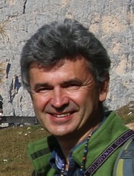 Peter Strobl合作论文数Commiss European Communities, Inst Sustainabil & Environm4Peter Haschberger合作论文数3
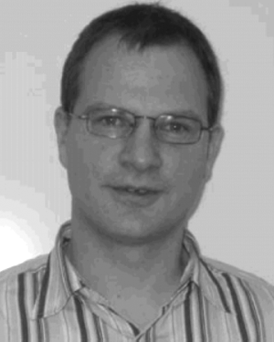 Jens Nieke合作论文数3Horst H Schwarzer合作论文数3P. Gege合作论文数2j piesbergen合作论文数2paul schotz合作论文数2
 Johannes Kaiser合作论文数The Climate and Environmental Research Institute NILU;SatFire Kaiser2
 Michael Schaepman合作论文数Remote Sensing Laboratories, Department of Geography, University of Zurich2Klaus I. Itten合作论文数2
 Karim Lenhard合作论文数2j gavira合作论文数1a neukom合作论文数1t schilliger合作论文数1
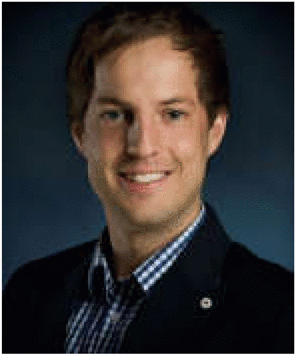 siebo reershemius合作论文数1
 Sebastian Fexer合作论文数1
 larschristian hauer合作论文数1olaf esmann合作论文数1Sebastian Kottmeier合作论文数1
 martin schutze合作论文数1
 Sabine Klinkner合作论文数1Jiri Fries合作论文数Dept Machine & Ind Design, VSB Tech Univ Ostrava1
 Simon Plass合作论文数German Aerospace Center;Institute of Communications and Navigation;German Aerospace Center, Institute of Communications and Navigation1
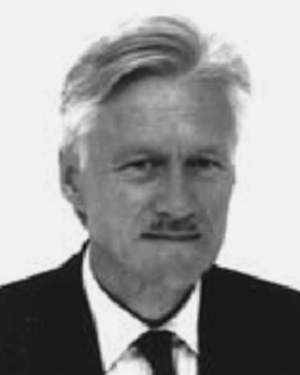 Klaus Itten合作论文数1
 Andreas Muller合作论文数university of michigan1
 Tobias Storch合作论文数Remote Sensing Technology Insitute, German Aerospace Center1
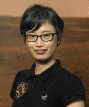 Tra-Mi Ho合作论文数1
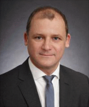 Tom Sproewitz合作论文数1P. Schötz合作论文数1Willem Jan Vreeling合作论文数1
 Federico Clazzer合作论文数1
 Andrea Munari合作论文数Institute of Communications and Navigation, German Aerospace Center DLR1Helmut Muhle合作论文数1Lieve De Vos合作论文数1James F Fries合作论文数1
 Walter Debruyn合作论文数1
 Rupert Muller合作论文数German Aerospace Center;Sensing Technology Institute;German Aerospace Center, Sensing Technology Institute1
 Jason Brazile合作论文数Remote Sensing Laboratories;Dept . of Geography;University of Zurich;Remote Sensing Laboratories, University of Zurich1Roland Meynart合作论文数1
 Pieter Kempeneers合作论文数Flemish Institute for Technological Research1
 Daniel Schlapfer合作论文数Remote Sensing Laboratories;Department of Geography;University of Zurich;Remote Sensing Laboratories, University of Zurich1




