This work reports and thoroughly discusses the results of an onsite trilateral comparison between a dual Josephson impedance bridge developed by METHS and the electronic fully digital impedance bridges developed by CMI and INRIMPOLITO. The target accuracies of the bridges are at the level of 10(-9) to 10(-8) for the former and at the level of parts in 10(7) for the latter. The bridges were tested with R : R and R : C standards, with nominal magnitudes of 12.9 k Omega, and with a quantum Hall resistance standard, in conditions suitable for the primary direct realization of the impedance units ohm and farad from ac quantum Hall resistance standards or from ac/dc calculable transfer resistance standards calibrated against dc quantum Hall resistance standards. The results were fully compatible at the expected level of uncertainty for what concerns the magnitude ratio, but phase measurements with R : C standards showed some incompatibilities.
In this article, we present a model that allows for significantly improving the impedance accuracy of calculable resistance standards. The proposed model extends the correction factor applied to the calculated four-terminal-pair impedance from the connector parts of the standard to the complete measurement circuit concerned by the applied voltage and current, respectively. In particular, we consider the cables and connectors contribution of the impedance bridge electronics. The model has been validated by performing: 1:1 and 0.1:1 impedance comparisons by means of two different typologies of calculable resistance standards. For the measurements, we relied on the accuracy of a digital bridge, which exploits the signals of two Josephson arbitrary waveform synthesizers (JAWSs). The frequency dependence of these new resistors has been analyzed over a range between 1 and 80 kHz.
The voltage errors related to ac leakage currents in Josephson arbitrary waveform synthesizer (JAWS) systems are significant contributors to the overall system accuracy. These ac leakage currents flow through paths (typically to ground) that are not part of the intended measurement circuit. This article examines output voltage discrepancies between two different but nominally identical circuit halves on a single JAWS circuit and shows that this discrepancy is dominated by ac leakage currents through the stray capacitance in the compensation leads. Methods to minimize these voltage errors will be discussed along with their associated limitations.
Nowadays, precision electrical measurements in AC voltage are mainly based on the use of Josephson arbitrary waveform synthesizers. Optimising the performance of such a system requires careful adjustment of the pulse train shape sent through the array. In this paper, we present a new method for tuning the various parameters of the pulse pattern generator when the Josephson array is operated in the zero-compensation mode. This method is based on the use of a two-terminalpair impedance bridge and can be fully automated. Preliminary results of this ongoing project show that the plateau width of the quantum-accurate output voltage increases by more than 2.5 times after optimisation provided by the described method.
This paper addresses the challenges associated with accurately measuring longitudinal impedance in a quantum Hall device. A novel bridge design capable of measuring both real and imaginary components of longitudinal impedance is introduced and applied for the first time. The measured inductance appears to be independent of both carrier density and mobility. Additionally, the inductance remains constant over the frequency range from 600 Hz to 50 kHz.
In this work, we present the results of an onsite trilateral comparison between a dual Josephson impedance bridge developed by METAS and the electronic fully-digital impedance bridges developed by CMI and INRIM-POLITO. The target accuracies of the bridges are at the 10(-8) level for the former and at the 10(-7) for the latter. Here we report the results of the calibration of a 10nF capacitance standard against a 12.9k Omega calculable resistance standard at 1233Hz, conditions suitable for the primary direct realization of the impedance units ohm and farad from AC quantum Hall resistance standards or from AC/DC calculable transfer resistance standards calibrated against DC quantum Hall resistance standards.
This paper describes hardware and software improvements of the SUT and METAS four-terminal-pair (4TP) sampling-based digital impedance bridges. These improvements are based on the use of a new dual output coaxial multiplexer and modified software controlling the bridge and procedure of complex voltage ratio measurement. The new setup provides an improved accuracy of impedance measurements due to good symmetry of the circuit and averaging results coming from two digitizers.
The first two impedance bridges based on pulse-driven Josephson voltage standards show the lowest uncertainties among digital bridges even comparable with state-of-the-art bridges using inductive voltage divider. In this paper, we will present the world's first comparison between these bridges. The observed difference between both systems measuring impedance ratios (C:C and R:R) is 6 nF/F and 6 n Omega/Omega at 1233.15 Hz. Up to 50 kHz, the measurements from both bridges agree within uncertainties, which are still below one part in 106 and dominated by cable effects.
This paper presents a one-to-one comparison of calculable resistance standards designed for radio frequency (RF) by using a digital bridge relying on the accuracy of two Josephson arbitrary waveform synthesizers (JAWS). In particular, the frequency dependence of these new resistors over a range between 1 kHz and 80 kHz is analyzed. Preliminary results show excellent consistency in the measurement of these artifacts. The corresponding measured impedance values deviate, relatively to the lowest frequency measurement, by a maximum of 0.1 mu Omega/Omega over the whole frequency range considered.
This article describes a method to model the impedance of a Haddad-type resistor over a frequency interval ranging from 10 to 200 MHz, hereafter defined as low frequency–radio frequency (LF–RF) range. To this end, novel resistor standards, of $1 \rm k \Omega $ and $100 \Omega $ , have been designed and manufactured with the aim of sharply identifying the nodes that define the impedance. Resistor modeling is divided into two main parts: the first one, describing the central coaxial core and the second part, describing the connectors through physical simulations and a subsequent analytical approach. The results show a remarkable good agreement between measured and modeled impedance over the whole considered frequency range. Uncertainty values allow for the traceability of the resistors up to high frequencies and for the calibration of commercial impedance analyzers within the LF–RF range.
This Good Practice Guide provides information for the realization of the farad from the quantum Hall resistance in graphene devices by using digital impedance bridges. The fabrication and characterization of graphene quantum Hall effect devices, the cryogenic environment required to achieve the quantization conditions, the digital impedance bridges and calibration procedures are reported. The guide is a deliverable of the Joint Research Project EMPIR 18SIB07 GIQS: Graphene Impedance Quantum Standard. This project received funding from the European Metrology Programme for Innovation and Research (EMPIR) co-financed by the Participating States and from the European Unions' Horizon 2020 research and innovation programme. Funder ID: 10.13039/100014132 , Grant no: 18SIB07.
This article describes two approaches for modeling impedances along the physical gap existing between the low-and high-frequency ranges. For this purpose, the physics of a Haddad-type resistor standard has been investigated taking into account the EM-field propagation and the effect of connectors. It turns out that above 30 MHz, the frequency dependence of the resistance is mainly dominated by the effects of the connector system. In addition, a new capacitor standard has been designed by means of physical simulations. In both approaches, a new method to exploit the information of the impedance matrix is presented. The use of this method considerably improves the impedance model. Preliminary results show a good agreement with measured data at low and high frequencies. A first estimation of the uncertainty has been also included in this article.
This paper presents a full characterization of a Dual Josephson Impedance Bridge (DJIB) at frequencies up to 80 kHz by using the DJIB to compare the best available impedance standards that are (a) directly traceable to the quantum Hall effect, (b) used as part of international impedance comparisons, or (c) believed to have calculable frequency dependence. The heart of the system is a dual Josephson Arbitrary Waveform Synthesizer (JAWS) source that offers unprecedented flexibility in high-precision impedance measurements. The JAWS sources allow a single bridge to compare impedances with arbitrary ratios and phase angles in the complex plane. The uncertainty budget shows that both the traditional METAS bridges and the DJIB have comparable uncertainties in the kilohertz range. This shows that the advantages of the DJIB, including the flexibility which allows the comparison of arbitrary impedances, the wide frequency range and the automated balancing procedure, are obtained without compromising the measurement uncertainties. These results demonstrate that this type of instrument can considerably simplify the realization and maintenance of the various impedance scales. In addition, the DJIB is a very sensitive tool for investigating the frequency-dependent systematic-errors that can occur in impedance construction and in the voltage provided by the JAWS source at frequencies greater than 10 kHz.
This paper describes the results of the calibration of a 100 pF capacitance standard performed at 1233 Hz. Two calibration chains were used. The classical calibration chain, involving a quadrature bridge and a 1:10 ratio bridge, and the faster and simpler calibration chain based on the Dual Josephson Impedance Bridge (DJIB). The results of the two procedures are in agreement within the uncertainty of the DJIB (u(k=1)=57 nF/F), which is slightly smaller than the uncertainty of the classical calibration chain presently in operation at METAS.
Pulse-driven Josephson junction arrays are quantum based voltage sources that can generate arbitrary waveforms with exceptional accuracy. However, wiring this perfect voltage source to a device under test drastically decrease these state of the art performances and causes deviations which scale quadratically with frequency and cable length. A load compensation bridge will be described in this paper that fully compensates the load of the Josephson arrays which is caused by the input impedance of the device under test. With this setup the frequency dependence up to a frequency of 80 kHz can be suppressed with an overall uncertainty of 2.8 μV/V.
Electrochemical impedance spectroscopy (EIS) is a widely applied non-destructive method of characterisation of Li-ion batteries. Despite its ease of application, there are inherent challenges in ensuring the quality and reproducibility of the measurement, as well as reliable interpretation and validation of impedance data. Here, we present a focus review summarising best metrological practice in the application of EIS to commercial Li-ion cells. State-of-the-art methods of EIS interpretation and validation are also reported and examined to highlight the benefits and drawbacks of the technique.
GIQS: Graphene Impedance Quantum Standard is a Joint Research Project of the European Metrology Programme for Innovation and Research (EMPIR). The project objective is to combine novel digital impedance measurement bridges with graphene-based ac quantum Hall resistance standards in a simplified cryogenic environment, to achieve simple, user-friendly quantum impedance standards suitable for primary realisation of impedance units in national metrology institutes, calibration centers, and the industry.
In 2017 the Consultative Committee for Electricity and Magnetism (CCEM) commissioned a key comparison of electrical capacitance standards, the second time this quantity has been compared since the implementation of the Mutual Recognition Agreement by the Comité International des Poids et Mesures (CIPM—MRA) in 1999. This comparison—CCEM-K4.2017—was piloted by the Bureau International des Poids et Mesures (BIPM) and included seven National Metrology Institutes (NMI) belonging to four Regional Metrology Organizations. The measuring scheme adopted for the comparison was that of a star comparison consisting of a set of bilateral comparisons between the participating NMIs and the BIPM, whose capacitance reference base served as a common reference. For each of the bilateral comparisons, the measurands were the capacitance values of 10 pF travelling standard capacitors belonging to the NMIs and, optionally, the values of 100 pF standards. All the participants have been chosen from those able to realize and maintain a representation of the farad at the best known level of accuracy. Four of them, including the BIPM, were taking their traceability from dc or ac quantum Hall effect standards and, the four others, from a calculable capacitor. The comparison results analysis have evidenced an agreement within about ±5 parts in 108 for the mandatory 10 pF measurements and within about ±10 parts in 108 for the optional 100 pF measurements. Also, excepted for one of the participants, a good agreement has been found for the ratio 100 pF:10 pF (within ±5 parts in 108). In addition to the comparison, it has been possible to evaluate the difference between the value of R K (von Klitzing constant) measured by electrical means from calculable capacitors and its last CODATA recommended value (CODATA 2014 adjustment). A difference of (43 ± 23) parts in 109 (k = 1) has been found which is consistent with the difference that can be computed from the experimental data used in the CODATA 2014 adjustment of fundamental constants. This report presents the details of the measurements and analysis having led to these results. Main text To reach the main text of this paper, click on Final Report. Note that this text is that which appears in Appendix B of the BIPM key comparison database kcdb.bipm.org/. The final report has been peer-reviewed and approved for publication by the CCEM, according to the provisions of the CIPM Mutual Recognition Arrangement (CIPM MRA).
The Josephson arbitrary waveform synthesizer is a quantum-based voltage source that can generate arbitrary waveforms with quantum accuracy. However, these state-of-the-art performances are drastically decreased by the wiring connecting the source to the device under test. This wiring introduces deviations from the Josephson voltage which scale quadratically with frequency. This paper describes a load compensation bridge that fully compensates the load of the Josephson arbitrary waveform synthesizer by the input impedance of the device under test and completely suppresses the frequency dependence up to a frequency of 80 kHz with an overall uncertainty of 2.8 mu V V-1.
This paper reviews the recent evolution of the measurement techniques in the area of impedance measurement from the Wheatstone bridge to the most advanced Josephson-based digital impedance bridge. The progress in the development of high sampling rate, high accuracy digital-to-analog and analog-to-digital converters has led to the development of digital impedance bridges that have profoundly modified the landscape of impedance metrology. Although these new bridges do not yet outperform the traditional transformer-based bridge in terms of accuracy, they significantly improve their measurement capabilities and flexibility by allowing a complete automation, a full coverage of the complex plane, arbitrary bridge ratios and extended frequency range. In addition, after the redefinition of the International System of Unit, they will contribute to the realization of the henry and the farad by establishing a direct link between the quantized Hall resistance and the capacitance or inductance standards.
 Blaise Jeanneret合作论文数Swiss Federal Office of Metrology OFMET54
 Alain Rüfenacht合作论文数Institute of Physics, University of Neuchâtel15
 Jürgen Schurr合作论文数13
 Luca Callegaro合作论文数Istituto Nazionale di Ricerca Metrologica12
 Felix Luond合作论文数7
 Eichenberger, A.合作论文数7
 Jan Kucera合作论文数7
 Alessandro Mortara合作论文数7
 Beat Jeckelmann合作论文数Swiss Federal Office of Metrology7
 Wood, B.M.合作论文数6
 Stephan Bauer合作论文数6
 Nathan E. Flowers-Jacobs合作论文数Superconductive Electronics Group, National Institute of Standards and Technology6
 Anna E. Fox合作论文数6
 Massimo Ortolano合作论文数Istituto Nazionale di Ricerca Metrologica Strada delle Cacce6
 Klaus Pierz合作论文数Zugehörigkeit unbekannt6
 Martina Marzano合作论文数Institute of Metrology, Electronics and Computer Science, University of Zielona Góra (UZG),5
 Erik Dierikx合作论文数5
 Barry M. Wood合作论文数National Research Council Canada5
 Marco Agustoni合作论文数4
 J. Nissila合作论文数4
 Yaowaret Pimsut合作论文数4
 Kruskopf Mattias合作论文数Physikalisch-Technische Bundesanstalt4
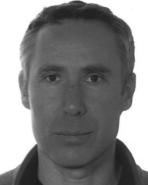 Pierre Gournay合作论文数Quantum Metrology Group, Laboratoire National de métrologie et dʼEssais, 29, avenue Roger-Hennequin, 78197 Trappes, France4
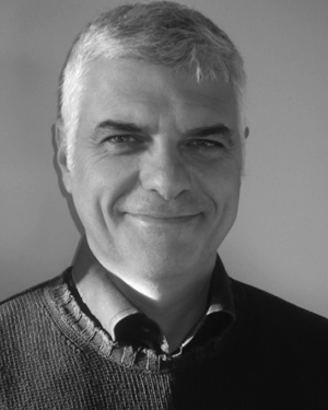 Vincenzo D'Elia合作论文数Politecnico di Torino4
 Thomas Schildknecht合作论文数Department Member, Astronomical Institute, University of Bern4
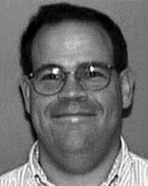 Paul D. Dresselhaus合作论文数Northrop Grumman Science and Technology Center4
 Gunnar Eklund合作论文数4T Springer合作论文数3Peter Coogan合作论文数3Miguel Neira合作论文数3Yuri Semenov合作论文数3Antonio Sanchez合作论文数3Janet Belliss合作论文数3Guenther Ramm合作论文数3Isabelle Blanc合作论文数3Mohd Saleem合作论文数3Yolanda Alvarez合作论文数3ZhongTai Qian合作论文数3Carlos Diaz合作论文数3Stephen Bryant合作论文数3J Melcher合作论文数3XiaoBing He合作论文数3Cheng Ding合作论文数3
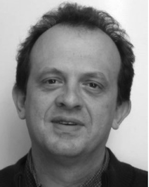 Olivier Thévenot合作论文数3
 Bryan C. Waltrip合作论文数3
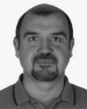 Enis Turhan合作论文数3
 Anil Saxena合作论文数3
 Kishan Thodkar合作论文数Phys. Dept., Univ. of Basel;c;Phys. Dept., Univ. of Basel3
 Stephen Giblin合作论文数3




