: Problems exist with the measurement of large aperture antennas due to the far field requirement. This paper discusses a new method to measure a phased array at about 1/10 the normal far field. The basic idea involves focusing the test array, at probe, antenna a distance R away from the aperture, and then, measuring an antenna pattern by moving the probe antenna on a constant focal arc given by R cos(Theta). This arc minimizes phase aberrations due to defocusing error. To minimize the amplitude errors, the pattern of the probe antenna is carefully matched in order to compensate for the 1/R variation induced amplitude error. The application of this technique will enable arrays to be measured in anechoic chambers, allowing convenient classified testing, while avoiding the effects of weather, and will reduce the risks inherent in the high power testing on transmit. The results of a computer simulation is presented that characterizes the validity and limitations of the technique.
: The radiation pattern of a curved phased array antenna is distorted when the beam is scanned. This is primarily due to the change of the appearance of the amplitude taper across the aperture which is a consequence of curvature. The approach described in this report, to correct for this phenomenon, is to adjust the aperture taper as a whole, rather than to adjust each individual radiating element separately. If an anti-symmetric taper is added in the proper proportion to a symmetric taper the original taper can be largely recovered. Typically the sum and difference aperture illuminations of an antenna can provide the needed symmetric and anti-symmetric functions. A relatively simple and practical technique of using the sum and difference networks in combination to correct for curvature effects is demonstrated. This technique uses a variable power divider to distribute the power is a prescribed proportion at an arbitrary scan angle to the sum and difference channels. The optimum amount of signal to be distributed to achieve the maximum restoration is found as a function of scan angle and curvature. The analysis is comprehensive, including effects due to the element pattern, antenna size, and the variation of apparent element density. Since attenuators are not used, the method has the added advantage of experiencing no loss of power. The technique can be used to improve any sum and difference illuminations. In this report cosine and sine illumination functions respectively are used.
: This report presents an analysis, design data and preliminary experimental results that demonstrate the use of metal grid angular filters for sidelobe suppression. These results indicate that sidelobe suppression in excess of 30 dB is achievable within 20 deg of the transmission pass band. (Author)
 Ronald L. Fante合作论文数10harvey tobin合作论文数6Richard Taylor合作论文数5nicholas karas合作论文数3Poirier J L合作论文数2Robert A. Shore合作论文数ARCON Corporation2Walter Rotman合作论文数2F. X. Canning合作论文数1JS Ju合作论文数1
 Jg Fikioris合作论文数1lancer f dennett合作论文数1
 Andreas C Cangellaris合作论文数Department of Electrical and Computer Engineering, The Grainger College of Engineering, University of Illinois at Urbana-Champaign1
 Roberto D. Graglia合作论文数Department of Electrical and Telecommunication Engineering, Politecnico di Torino1Greene, K.合作论文数1
 Constantine Balanis合作论文数School of Electrical, Computer and Energy Engineering, Arizona State University;Ira A. Fulton Schools of Engineering, Arizona State University1
 Giovanni Ghione合作论文数Department of Electronics and Telecommunications, Politecnico di Torino1
 Henry L Bertoni合作论文数Department of Electrical and Computer Engineering, Tandon School of Engineering, NYU1Gothard, G.K.合作论文数1Cavcey, K.合作论文数1German, F.J.合作论文数1
 Ahmed Kishk合作论文数Department of Electrical and Computer Engineering, Gina Cody School of Engineering and Computer Science, Concordia University;Department of Electrical Engineering, University of Mississippi1
 George V. Eleftheriades合作论文数The Edward S. Rogers Sr. Department of Electrical and Computer Engineering, Faculty of Applied Science and Engineering, University of Toronto1
 Naoki Inagaki合作论文数1
 Apisak Ittipiboon合作论文数1
 Luc Knockaert合作论文数Ghent University1
 Christophe Caloz合作论文数Department of Electrical Engineering, Faculty of Engineering Science, KU Leuven1
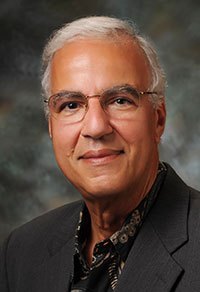 Magdy F. Iskander合作论文数Hawaii Advanced Wireless Technologies Institute, University of Hawaii at Manoa1
 Jiro Hirokawa (廣川二郎)合作论文数Department of Electrical and Electronic Engineering, School of Engineering, Tokyo Institute of Technology1
 Vikram Jandhyala合作论文数University of Washington1
 Darko Kajfez合作论文数The School of Engineering at Ole Miss, University of Mississippi1
 Lawrence Carin合作论文数Agency for Science, Technology and Research1Herbert V. Hitney合作论文数1
 Stephen Gedney合作论文数University of Colorado Denver1William T. Joines合作论文数1Rebekah Kipp合作论文数1
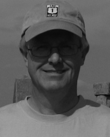 Robert T. Johnk合作论文数1
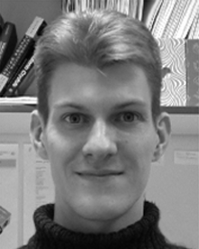 Timothy J. Karle合作论文数Laboratoire de Photonique et de Nanostructures;University of Ghent;Laboratoire de Photonique et de Nanostructures, University of Ghent1
 Katsuyuki Haneda合作论文数Department of Electronics and Nanoengineering, School of Electrical Engineering, Aalto University;Helsinki University of Technology1
 Stuart G. Hay合作论文数The Commonwealth Scientific and Industrial Research Organisation1
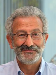 Nader Engheta合作论文数Department of Physics and Astronomy, College of Arts & Sciences, University of Pennsylvania;Department of Electrical & Systems Engineering, University of Pennsylvania;School of Engineering and Applied Science, University of Pennsylvania1Zoltan J. Cendes合作论文数1
 Russell Gough合作论文数1
 Joseph R. Guerci合作论文数Defense Advanced Research Projects Agency1
 Randy L. Haupt合作论文数Department of Electrical Engineering and Computer Science, Colorado School of Mines1
 Ercument Arvas合作论文数School of Engineering and Natural Sciences, Istanbul Medipol University1
 Jeffrey S. Herd合作论文数Lincoln Laboratory, Massachusetts Institute of Technology1
 Robert J Mailloux合作论文数1Jose A. Encinar合作论文数1D. J. Donohue合作论文数1




