The AFRL Shiva Star capacitor bank (1300 microfarads, up to 120 kilovolts) operated typically with 4 to 5 megajoules of electrically stored energy, with axial discharge currents of 10 to 15 megamps, and current rise times of approximately 10 microseconds, has been used to drive metal shell (solid liner) implosions in several geometries, including long cylindrical designs, which are suitable for compression of axial magnetic fields to multi-megagauss levels. Such imploding liners are also suitable for compressing magnetized plasmas to magneto-inertial fusion conditions. MagnetoInertial Fusion (MIF) approaches take advantage of embedded magnetic field to improve plasma energy confinement by reducing thermal conduction relative to conventional inertial confinement fusion (ICF). MIF reduces required implosion speed and convergence ratio relative to ICF. AFRL, its contractors and collaborating institutions LANL, UNM, and UNR have developed one version of magnetized plasmas at pre-compression densities, temperatures, and magnetic fields that may be suitable for such compression. These are Field Reversed Configurations (FRCs). This effort reliably formed, translated, and captured FRCs in magnetic mirrors inside10 cm diameter, 30 cm long, mm thick metal shells or liners in preparation for subsequent compression by liner implosion; imploded a liner with an interior magnetic mirror field, obtaining evidence for compression of 1.36 T field to approximately 500 T; performed a full system experiment of FRC formation, translation, capture, and imploding liner compression operation; identified by comparison of 2D-MHD simulation and FRC capture experiments factors limiting the closed-field lifetime of FRCs to about half that required for good liner compression of FRCs to multi-keV, 10<^>19 ion/cm<^>3, high energy density plasma (HEDP) conditions; and designed and prepared hardware to increase that closed field FRC lifetime to the required amount. Those lifetime extension experiments have obtained imaging evidence of FRC rotation (which is a phenomenon that limits such closed field lifetimes), and of initial rotation control measures slowing and stopping such rotation. These and the results of subsequent closed field plasma lifetime and compression experiments and related simulations will be discussed.
In 1991, Turchi et al. [1] reported evidence for a 2,000 km/s aluminum plasma that originated from the upstream boundary of a wire array armature in a plasma flow switch (PFS) [2]. The 2008 article by Turchi et al. [3] posits that if such high Z plasma could instead be composed of deuterium or a deuterium-tritium mixture then the resultant multi-keV plasma would make an effective target for magnetized plasma compression to fusion conditions. This report documents several exploratory tests executed in an effort to achieve significant energy transfer from a plasma flow switch to a deuterium plasma. The first phase of this research concentrated on extension of the earlier work [1, 2] to a lower current system that would emulate the PFS used in series with an imploding liner load. The apparatus was also modified to permit pulsed injection of deuterium gas along the insulated coaxial electrodes between the PFS armature and the vacuum power feed. In analyzing the armature behavior, the initial conditions used in 2-D axisymmetric MHD simulations to approximate the wire-array/polymer film composite armature resulted in significant uncertainty in the validity of the calculations. This uncertainty confounded efforts to improve the opening switch behavior of the armature. Low density foams, commonly used in other high energy density plasma experiments, were seen as a candidate material for the armature that would facilitate greater fidelity between simulations and the experiment. Two subsequent tests were conducted using foam armatures. In both cases, current prematurely shunted upstream in the vacuum feed. Several possible causes were explored for the shunting of the current. Among the modifications implemented, the gas injection system was altered to increase both the quantity of gas adjacent to the armature while facilitating an increased pressure gradient between the armature and the current feed. A series of low energy shots were conducted to examine the impact of several proposed design modifications on current delivery to the armature. One conclusion of these experiments was that it has been very difficult to forestall breakdown in the injected gas as required by Turchi et al. [3]. Nevertheless, two experiments were conducted to evaluate performance with foam armatures. Both experiments exhibited good current delivery to the armature, behaving initially like the low energy experiments. The magnetic flux convected downstream was greater than in any of the prior experiments, though significant work remains to demonstrate the ultra-high-speed plasma flow concept.
A system of two FCG's coupled via "flux-trapping" is described. The driver FCG, designated SAM, was custom-designed for this application. The output of SAM is a single-turn loop that is tightly coupled to the first winding section of a larger FCG, designated JILL. The single-turn driver loop, coupled to 35 turns of the input winding of JILL, provides a calculated flux gain of 28.For the first experimental test of the SAM/JILL system, the SAM generator was seeded with 1.0 kA (flux 0.29 Wb) and produced a current of 472 kA (flux 0.10 Wb) in the coupling loop at crowbar time of the JILL generator.Based on the calculated mutual inductance of 5.95 mu H, the JILL generator began operation with a seed flux of 2.81 Wb. With this seed flux, the expected output current for JILL driving a 0.8 mu H load is 1.8 MA. The measured output current was 884 kA, roughly one half of the expected current. Analysis of the I-dot data from the test shows that this low performance was due to multiple electrical breakdowns in the JILL generator during the interval when the armature-stator contact point was underneath the coupling loop.Subsequent analysis suggests that the electrical breakdowns were the result of flux compression in the coupling loop. Details of the experiment and analysis will be presented. A modification to the SAM/JILL apparatus is proposed to eliminate electrical breakdown.
The performance of a high-gain FCG is often limited by internal electrical breakdown caused by the high voltage generated during operation. Modern diagnostic techniques provide the opportunity to diagnose internal breakdowns so that generator designs can be improved. This paper describes the internal breakdowns observed in the JAKE FCG developed at the AFRL during the late 1990's. A revision to the stator winding pattern of the JAKE generator has led to improved control of the internal voltage. Designated JILL, the revised generator has substantially better flux transport efficiency, particularly at higher seed current. The techniques employed to design the new stator winding and the results of development testing are presented.
The Air Force Research Laboratory (AFRL) maintains an extensive capability for the design, analysis, construction and testing of explosive pulsed power (EPP) components. Three flux compression generators (FCGs) were designed as part of an EPP technology development effort sponsored by AFRL and the Defense Advanced Research Projects Agency (DARPA). A secondary-stage, high-current FCG was designed to deliver 10 MA into a nominal load inductance of 80 nH from an initial generator inductance of 1.6 muH that is seeded with 1 MA. We have also developed a coaxial FCG to deliver more than 20 MA into a 2 nH load. The initial flux in the coaxial chamber (60 nH at 1.5 MA) is compressed uniformly using a copper armature, which is simultaneously initiated using a slapper detonator. Either of these two FCGs can be seeded with a third generator design: a high-gain, helical FCG. This model serves as our workhorse generator capable of delivering 2 MA into a 0.5 muH inductive load. It has also been operated into load inductances ranging from 0.1 to 2.0 muH with comparable flux delivery. All experiments are conducted on an explosive test range located on Kirtland Air Force Base [1]. The design effort is supported by powerful computer modeling using CAGEN [2], CALE and MACH2. Design features for all three FCGs are presented in this paper with results from recent explosive tests.
The Air Force Research Laboratory has developed and tested a variety of explosive driven pulsed power devices over the past twenty-two years. Testing is performed primarily at a dedicated facility located at Chestnut Site on Kirtland Air Force Base. The facility is described in this paper, including details of recent upgrades.
 James H. Degnan合作论文数5
 Sean K. Coffey合作论文数5J. V. Parker合作论文数5Lehr, F.M.合作论文数4Gerald F. Kiuttu合作论文数3Gale, D.合作论文数3w sommars合作论文数3t cavazos合作论文数2Kostora, M.合作论文数2Lerma, A.合作论文数2
 Domonkos Matthew合作论文数2
 Alan Gene Lynn合作论文数2Roderick, N.合作论文数2White, W.合作论文数2Amdahl, D.J.合作论文数2Camacho J F合作论文数2Sherry D. Frese合作论文数2Volodymyr Makhin合作论文数2Thomas Montoya合作论文数1brian blasy合作论文数1Peter J. Turchi合作论文数1p r robinson合作论文数1d ralph合作论文数1
 Weber, T.合作论文数1Sears, J.A.合作论文数1
 Peter J Turchi合作论文数1
 Paul E. Adamson合作论文数1
 Stephan Fuelling合作论文数1Cavazos, T.合作论文数1John Mccullough合作论文数1Grabowski T C合作论文数1
 Glen Wurden合作论文数Los Alamos National Laboratory1Wesley Tucker合作论文数1W. J. Waganaar合作论文数1
 Bruno S. Bauer合作论文数1D. G. Schroen合作论文数1
 Christopher A. Grabowski合作论文数1
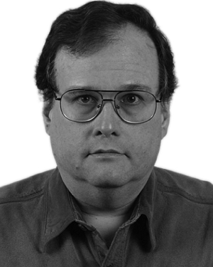 Edward L. Ruden合作论文数1
 Michael H. Frese合作论文数1Robert C. Cooksey合作论文数1
 Thomas Intrator合作论文数Los Alamos National Laboratory1
 Michael Frese合作论文数Asia School of Business;Dept. of Management & Organization, Leuphana University of Lueneburg1




