The primary purpose of the InSight Instrument Deployment System (IDS) on the Mars InSight Lander, which landed in November 2018, was to deploy three payloads: a seismometer (SEIS), a heat flow probe (HP3), and a wind and thermal shield (WTS), to the Martian surface. The system consists of the Instrument Deployment Arm (IDA), Instrument Deployment Camera (IDC) on the forearm of the IDA, and the Instrument Context Camera (ICC). A core functionality of the IDS that was critical to the success of the deployments was the ability to use only the single camera on the arm and monocular localization methods to calculate the poses of each of the instruments before and after deployment. Given that the ICC has a fisheye lens and was located under the lander, relatively far from the deployment sites, only the IDC was useful for quantitative localization. Knowledge of the exact pose of each instrument was critical for any activity that involved interacting with the instruments, such as the deployment of the WTS over SEIS to protect the instrument and reduce environmental noise. Additionally, knowledge of the instrument poses was necessary to meet the mission's science objectives, used to accept the instrument deployment sites, and to create noise models used to help scientists interpret the instrument data. While the technology was employed on this mission to allow for stereo data to be captured by moving the single camera over a known baseline, physical arm constraints, operational constraints, and a desire for independent verification necessitated robust methods of monocular localization. Two different methods of monocular localization were developed and employed for the deployment phase of the mission. Fiducial localization which used precisely measured, round single point fiducials along with more robust AprilTag fiducials that provide 5 points as well as an independent orientation from each fiducial. Along with quantitative analysis, grapple localization was developed to confirm the localization by physically lining up the IDA grapple with the hook on each instrument. This paper will discuss the motivation, implementation, and execution of each monocular localization technique employed by the IDS. Additionally, it will detail the results and error sources identified throughout the mission using downlinked images and measurements from the InSight lander and InSight Testbed.
NASA's InSight Mars Lander, which landed on Mars in November 2018, completed the first precision robotic instrument placement on a planetary surface as part of its instrument deployment phase. Using the Instrument Deployment Arm (IDA), InSight deployed the two key science payload elements, a seismometer (SEIS) and heat flow probe (HP3), as well as a wind and thermal shield (WTS) placed over the seismometer. SEIS and HP3 are tethered to the lander for both power and communications purposes. Placement accuracy of the instrument deployment was essential for successful realization of the mission's core science objectives. In order to meet the requirements for placement accuracy, we worked to understand and mitigate the factors contributing to placement error. Those factors include but are not limited to: the IDA position control error, the error in the computation of the digital elevation model (DEM), the targeting error in selecting the desired placement site, and each instruments ground interaction. In particular, the SEIS placement accuracy was greatly affected by the placement of its tether on the terrain during the instrument deployment. The SEIS tether is a stack of six flex cable belts attached at one end to the lander deck. At the other end, the tether is looped and attached to the instrument with a load shunt assembly (LSA) designed to isolate signals detected by the instrument from any noise created by the tether due to thermoelastic deformation, atmospheric events, etc. Additionally, the tether contains a field joint and a pinning mass (which grounds the tether and is used to manipulate the tether with the robotic arm post-placement). In our validation and verification (V&V) activities, we determined that the interaction of the SEIS tether on the terrain greatly affected our instrument placement accuracy. In order to understand and minimize this effect, we created a mathematical model of the SEIS tether and then used that model to develop the deployment sequences. Ultimately, our sequences deployed both the tether and the instrument on the Martian surface, taking into consideration the whole system for a successful deployment. This paper will discuss the motivation and details of the implementation of the SEIS tether model and the ways in which the SEIS tether impacted placement accuracy in certain configurations. It will also show results from testing this model on Earth and deploying SEIS to the Martian surface on sol 22 of InSight's mission.
The InSight Mars Lander is equipped with an Instrument Deployment System (IDS) and science payload with accompanying auxiliary peripherals mounted on the Lander. The InSight science payload includes a seismometer (SEIS) and Wind and Thermal Shield (WTS), heat flow probe (Heat Flow and Physical Properties Package, HP3) and a precision tracking system (RISE) to measure the size and state of the core, mantle and crust of Mars. The InSight flight system is a close copy of the Mars Phoenix Lander and comprises a Lander, cruise stage, heatshield and backshell. The IDS comprises an Instrument Deployment Arm (IDA), scoop, five finger "claw" grapple, motor controller, arm-mounted Instrument Deployment Camera (IDC), lander-mounted Instrument Context Camera (ICC), and control software. IDS is responsible for the first precision robotic instrument placement and release of SEIS and HP3 on a planetary surface that will enable scientists to perform the first comprehensive surface-based geophysical investigation of Mars' interior structure. This paper describes the design and operations of the Instrument Deployment Systems (IDS), a critical subsystem of the InSight Mars Lander necessary to achieve the primary scientific goals of the mission including robotic arm geology and physical properties (soil mechanics) investigations at the Landing site. In addition, we present test results of flight IDS Verification and Validation activities including thermal characterization and InSight 2017 Assembly, Test, and Launch Operations (ATLO), Deployment Scenario Test at Lockheed Martin, Denver, where all the flight payloads were successfully deployed with a balloon gravity offload fixture to compensate for Mars to Earth gravity.
A complete robotic system software architecture is presented including elements of an operator control station and the Intelligent Robotics System Architecture (IRSA) for embedded robotic system software. The architecture has been implemented for various robotics testbeds and prototypes including comet surface sample return sampling validation, Europa Lander sampling autonomy, Mars 2020 mission testbeds, and the RoboSimian mobile robot. IRSA provides a reference architecture for development of complete robotics systems or systems with knowledge of what subset of capabilities are provided. The architecture is presented and its use in various applications is described. The system includes operator side components including sequence generation and simulation and robot side components such as hierarchical behaviors and sequencing.
The development of the Sampling and Caching Subsystem (SCS) of the Mars 2020 Rover Mission is highly dependent on testing of prototype hardware and software operating in explicit conditions as part of integrated testbeds. To achieve relevant integration of hardware and software while maintaining rapid algorithm development capabilities and high testing throughput, the Controls and Autonomy for Sample Acquisition and Handling (CASAH) software system was developed. CASAH is an implementation of the Intelligent Robotics System Architecture (IRSA), which mimics JPL Flight Software (FSW) in that it is divided into modules that run separate processes that communicate via message passing, each module is assigned an owner that is a single developer, and the operator initiates requests via a text-based interface that interprets sequences of commands. IRSA enables a modular breakdown of CASAH that follows that of 2020 Flight Software, so developers can take an algorithm from a module in CASAH and re-code it into the same module in FSW. As deployment of CASAH has grown to ten testbeds - each with different hardware and objectives - bottom-up design decisions have been intentionally made to keep the system lightweight and maintainable by a very small team. To date, CASAH has been used to run 1393 different tests. This work describes CASAH, the testbeds and functionality it supports, the tools used to manage the development and sharing of code, and the features of the software. Lessons learned over the past three years of development and deployment are provided.
Planetary surface science operations performed by robotic space systems frequently require pointing cameras at various objects and moving a robotic arm end effector tool toward specific targets. Earlier NASA Mars Exploration Rovers did not have the ability to compute actual coordinates for given object coordinate frame names and had to be provided with explicit coordinates. Since it sometimes takes hours to more than a day to get final approval of certain calculated coordinates for command uplink via the Earth-based mission operations procedures, a highly desired enhancement for future rovers was to have the onboard automated capability to compute the coordinates for a given frame name. The Mars Science Laboratory (MSL) rover mission is the first to have a centralized coordinate transform database to maintain the knowledge of spatial relations. This onboard intelligence significantly simplifies communication and control between Earth-based human mission operators and the robotic rover on Mars by supporting higher level abstraction of commands using object and target names instead of coordinates. More specifically, the spatial relations of many object frames are represented hierarchically in a tree data structure, called the frame tree. Individual frame transforms are populated by their respective modules that have specific knowledge of the frames. Through this onboard centralized frame tree database, client modules can query transforms between any two frames and support spacecraft commands that use any frames maintained in the frame tree. Various operational examples in the MSL mission that have greatly benefitted from this onboard centralized frame tree database are presented.
This chapter presents recent advances in space robotics autonomy technology, some of which have been successfully deployed in NASA missions. In-situ planetary exploration presents unique challenges that can only be addressed by using autonomy technologies. The process of developing command sequences to send to an unmanned planetary spacecraft has always been time-consuming and laborintensive. For future long-duration planetary missions reducing the operations team workload is paramount owing to considerations for human factors, maximizing science return, and optimizing mission resources. Autonomy is a key enabling technology for future long-duration planetary missions such as human precursor missions to Mars, Mars Sample Return missions, Comet Sample Return missions, and in-situ missions to Titan and Europa. With the unprecedented back-to-back successful landing on Mars of the NASA’s Mars Exploration Rovers (MERs), Spirit and Opportunity (2004), Phoenix Mars Lander (2008), and Mars Science Laboratory (2012) over the last decade the robotics autonomous systems community has celebrated several onboard autonomous technologies milestones.
A sample acquisition and caching architecture has been developed for the proposed Mars 2020 mission that acquires samples directly into sample tubes in coring bits. Sample tubes are inserted and removed from the bits, seals are inserted into the tubes, and the tubes are placed in the sample canister. This paper describes initial algorithms, implementation, and test results where sample tube transfer operations are performed using the sampling arm where the tube gripper is on the arm turret with the sampling tool. The testbed utilizes a robotic arm with harmonic drives in the actuators which then provide an arm with low backlash and high resolution of motion. A six-axis force-torque sensor provides force feedback for the tube transfer operations. The results show that the tube transfer operations can be done robustly using the existing testbed robotic arm and caching hardware. Future work is described which will investigate the effects on robustness of the tube transfer with reduced capability robotic arm and force sensing.
Abstract: It is being tried to control robot arm using brain signal in the field of brain-machine interface (BMI). Thisstudy is focused on applying guidance laws for efficient robot arm control using 3D coordinates obtained from Mag-netoencephalography (MEG) signal which represents movement of upper limb. The 3D coordinates obtained frombrain signal is inappropriate to be used directly because of the spatial difference between human upper limb and robotarm’s end-effector. The spatial difference makes the robot arm to be controlled from a third-person point of view withassist of visual feedback. To resolve this inconvenience, guidance laws which are frequently used for tactical ballisticmissile are applied. It could be applied for the users to control robot arm from a first-person point of view whichis expected to be more comfortable. The algorithm which enables robot arm to trace MEG signal is provided in thisstudy. The algorithm is simulated and applied to 6-DOF robot arm for verification. The result was satisfactory anddemonstrated a possibility in decreasing the training period and increasing the rate of success for certain tasks suchas gripping object.Key words: Brain Signal, Brain-Machine Interface (BMI), Robot Arm, Guidance Law
The design methodologies of using sequence diagrams, multi-process functional flow diagrams, and hierarchical state machines were successfully applied in designing three MSL (Mars Science Laboratory) flight software modules responsible for handling actuator motions of the CHIMRA (Collection and Handling for In situ Martian Rock Analysis), IC (Inlet Covers), and DRT (Dust Removal Tool) mechanisms. The methodologies were essential to specify complex interactions with other modules, support concurrent foreground and background motions, and handle various fault protections. Studying task scenarios with multi-process functional flow diagrams yielded great insight to overall design perspectives. Since the three modules require three different levels of background motion support, the methodologies presented in this paper provide an excellent comparison. All three modules are fully operational in flight.
One of the goals of the Mars Science Laboratory (MSL) mission is to collect powderized samples from the interior of rocks in order to deliver these samples to onboard science instruments. This paper describes the algorithms and software used to control the drill, which is the component of the sample collection and delivery system that directly interacts with rocks to create and acquire powderized samples from their interior. This is the first time that autonomous drilling of rocks has ever been performed on another planet. One of the most important components of the algorithm used for drilling is a force feedback control system used to regulate the force applied to the rock during drilling. This algorithm and all of the other algorithms and software used to enable the process of robustly, efficiently, and autonomously drilling into rocks with a priori unknown and widely varying properties are described in detail in this paper. Results are shown from drilling rocks using the drill software on testbed hardware on Earth as part of the software development process. Results are also shown from the first holes drilled with the flight vehicle on Mars, thus successfully demonstrating the first extraterrestrial autonomous drilling of a rock.
The FM (Frame Manager) flight software module is responsible for maintaining the frame tree database containing coordinate transforms between frames. The frame tree is a proper tree structure of directed links, consisting of surface and rover subtrees. Actual frame transforms are updated by their owner. FM updates site and saved frames for the surface tree. As the rover drives to a new area, a new site frame with an incremented site index can be created. Several clients including ARM and RSM (Remote Sensing Mast) update their related rover frames that they own. Through the onboard centralized FM frame tree database, client modules can query transforms between any two frames. Important applications include target image pointing for RSM-mounted cameras and frame-referenced arm moves. The use of frame tree eliminates cumbersome, error-prone calculations of coordinate entries for commands and thus simplifies flight operations significantly.
Surface deflections in exterior panel have a great effect on the external appearance of automobiles. Usually, they are occurred on large flat panels containing sudden shape changes and shows very small amplitude. Traditional methods for detecting surface deflections on stamped automobile panels are scratching the surface with a wheatstone with oil, rubbing the surface with technician's fingers, or reflecting light on the surface. All of these methods rely on a technician's sense. In this study, a curvature based method was proposed to detect and quantify the surface deflection. The measure of surface deflection was defined as the variation of curvature difference between tool and blank. The degree of surface deflection can be predicted by the correlation between the proposed measure and visual inspection. Today's simulation code has enough accuracy to predict surface deflection by using the proposed method. The appropriate simulation method to find the surface deflections accurately were studied. As a verification example, a shallow rectangular drawing with rectangular embossing was studied. The corresponding experiment was carried out. The simulation and experiment were compared and investigated to prove the effectiveness of the proposed method and the effectiveness of prediction.
This paper presents the development, validation, and deployment of the visual target tracking capability onto the Mars Exploration Rover (MER) mission. Visual target tracking enables targeted driving, in which the rover approaches a designated target in a closed visual feedback loop, increasing the target position accuracy by an order of magnitude and resulting in fewer ground-in-the-loop cycles. As a result of an extensive validation, we developed a reliable normalized cross-correlation visual tracker. To enable tracking with the limited computational resources of a planetary rover, the tracker uses the vehicle motion estimation to scale and roll the template image, compensating for large image changes between rover steps. The validation showed that a designated target can be reliably tracked within several pixels or a few centimeters of accuracy over a 10-m traverse using a rover step size of 10% of the target distance in any direction. It also showed that the target is not required to have conspicuous features and can be selected anywhere on natural rock surfaces excluding rock boundary and shadowed regions. The tracker was successfully executed on the Opportunity rover near Victoria Crater on four distinct runs, including a single-sol instrument placement. We present the flight experiment data of the tracking performance and execution time. © 2009 Wiley Periodicals, Inc.
Visual target tracking (VTT) software has been incorporated into Release 9.2 of the Mars Exploration Rover (MER) flight software, now running aboard the rovers Spirit and Opportunity. In the VTT operation (see figure), the rover is driven in short steps between stops and, at each stop, still images are acquired by actively aimed navigation cameras (navcams) on a mast on the rover (see artistic rendition). The VTT software processes the digitized navcam images so as to track a target reliably and to make it possible to approach the target accurately to within a few centimeters over a 10-m traverse.
Visual Target Tracking (VTT) has been implemented in the new Mars Exploration Rover (MER) Flight Software (FSW) R9.2 release, which is now running on both Spirit and Opportunity rovers. Applying the normalized cross-correlation (NCC) algorithm with template image magnification and roll compensation on MER Navcam images, VTT tracks the target and enables the rover to approach the target within a few cm over a 10 m traverse. Each VTT update takes 1/2 to 1 minute on the rovers, 2-3 times faster than one Visual Odometry (Visodom) update. VTT is a key element to achieve a target approach and instrument placement over a 10-m run in a single sol in contrast to the original baseline of 3 sols. VTT has been integrated into the MER FSW so that it can operate with any combination of blind driving, Autonomous Navigation (Autonav) with hazard avoidance, and Visodom. VTT can either guide the rover towards the target or simply image the target as the rover drives by. Three recent VTT operational checkouts on Opportunity were all successful, tracking the selected target reliably within a few pixels.
A team of JPL researchers has analyzed stereoscopic vision software and produced a document describing its performance. This software is of the type used in maneuvering exploratory robotic vehicles on Martian terrain. The software in question utilizes correlations between portions of the images recorded by two electronic cameras to compute stereoscopic disparities, which, in conjunction with camera models, are used in computing distances to terrain points to be included in constructing a three-dimensional model of the terrain. The analysis included effects of correlation- window size, a pyramidal image down-sampling scheme, vertical misalignment, focus, maximum disparity, stereo baseline, and range ripples. Contributions of sub-pixel interpolation, vertical misalignment, and foreshortening to stereo correlation error were examined theoretically and experimentally. It was found that camera-calibration inaccuracy contributes to both down-range and cross-range error but stereo correlation error affects only the down-range error. Experimental data for quantifying the stereo disparity error were obtained by use of reflective metrological targets taped to corners of bricks placed at known positions relative to the cameras. For the particular 1,024-by-768-pixel cameras of the system analyzed, the standard deviation of the down-range disparity error was found to be 0.32 pixel.
 Paul S. Schenker合作论文数TTG Imaging Solutions14
 Khaled S. Ali合作论文数8
 Adnan Ansar合作论文数Jet Propulsion Laboratory, California Institute of Technology7
 Lawrence W. Stark合作论文数Department of Physiological Optics and Engineering, University of California, Berkeley6
 Robert D. Steele合作论文数6
 john r nickolls合作论文数5
 Joseph Carsten合作论文数5Antal K. Bejczy合作论文数5
 Steven Venema合作论文数Dept . of Electrical Engineering;University of Washington5
 Daniel M. Helmick合作论文数Jet Propulsion Laboratory;University of Minnesota;Dept . of Computer Science and Engineering;Jet Propulsion Laboratory, University of Minnesota5Ashitey Trebi-Ollennu合作论文数Group Leader, Senior Member of Engineering Staff5
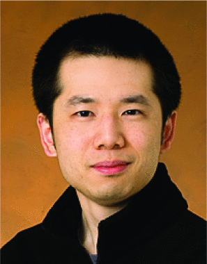 Steven Myint合作论文数4
 Philip Bailey合作论文数4
 Cristina Sorice合作论文数4
 Jeffrey J. Biesiadecki合作论文数4
 Issa A.D. Nesnas合作论文数Jet Propulsion Laboratory4Chris Leger合作论文数Jet Propulsion Laboratory
M;S T1722
4800 Oak Grove Drive
Pasadena, CA 911094
Issa A.D. Nesnas合作论文数Jet Propulsion Laboratory4Chris Leger合作论文数Jet Propulsion Laboratory
M;S T1722
4800 Oak Grove Drive
Pasadena, CA 911094 Blake Hannaford合作论文数Between Jobs Engineering;Department of Electrical & Computer Engineering, University of Washington;Applied Dexterity Inc.;Blake Hannaford Consulting;SPI Surgical4
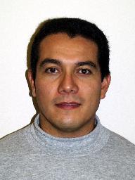 Antonio Díaz Calderón合作论文数Applied Physics Laboratory, Johns Hopkins University4john zapisek合作论文数3
 J. Balaram合作论文数3
 Samad Hayati合作论文数Jet Propulsion Laboratory, California Institute of Technology3zoltan f szakaly合作论文数2wing lo合作论文数2jue chang合作论文数2R. Deen合作论文数2H. Abarca合作论文数2
 Jeffrey Umland合作论文数2Omair Khan合作论文数2eliot wegbreit合作论文数2
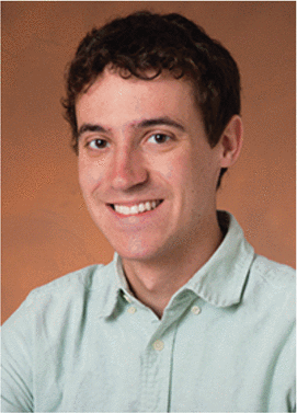 Sawyer Brooks合作论文数2
 Grace Lim合作论文数2
 Cheng Yang (杨成)合作论文数School of Information and Communication Engineering, Communication University of China2
 Vieira, P.合作论文数2Chalfant, E.C.合作论文数2Callum, L.合作论文数2Rhee H S合作论文数2
 Paolo Fiorini合作论文数Department of Engineering for Innovation Medicine, University of Verona;Needleye Robotics Srl2Haya Zak合作论文数2
 Andrew Liu合作论文数MIT Man Vehicle Lab2Paul Backes合作论文数Jet Propulsion Laboratory2
 Wyatt Ubellacker合作论文数Control and Dynamical Systems and the Department of Mechanical and Civil Engineering, California Institute of Technology2Frank Tendick合作论文数University of California, San Francisco2
 Homayoun Seraji合作论文数Jet Propulsion Laboratory, National Aeronautics and Space Administration;California Institute of Technology2
 Arturo L. Rankin合作论文数2Stephen R. Ellis合作论文数NASA Ames Research Center2




