For more than half a century, researchers around the world have been engaged in attempts to achieve fusion ignition as a proof of principle of various fusion concepts. As recently reported, a burning plasma state, where the alpha-heating in the plasma is the primary source of heating, was achieved in laboratory experiments. Following the Lawson criterion, an ignited plasma is one where the fusion heating power is high enough to overcome all the physical processes that cool the fusion plasma, creating a positive thermodynamic feedback loop with rapidly increasing temperature. In inertially confined fusion, ignition is a state where the fusion plasma can begin ``burn propagation'' into surrounding cold fuel, enabling the possibility of high energy gain. While ``scientific breakeven'' (i.e. unity target gain) has not yet been achieved, this talk reports the first controlled fusion experiment on the National Ignition Facility to produce capsule gain greater than unity (here 5.8) and reach ignition by many different formulations of the Lawson criterion. In the talk, we will discuss some key basic physics inertial confinement fusion (ICF) principles behind the burning plasma and ignition results as well as discuss future challenges.
Diagnostics play a very important role in the modern Tokamak where optimum performance is essential. To achieve this, the device must be equipped with reliable and robust sensors and instrumentation that allow the operation envelope to be fully explored. Development of these diagnostics to maintain this reliability is necessary. Further to the development, the systems must be integrated in a way that maintains their performance while simultaneously satisfying the key requirements needed for safety and tokamak operation. ITER will have 50 diagnostics; almost all of which are utilized primarily for the real-time operation of the tokamak. While there is still much work to do, to date, significant progress has been made in the development of these systems. The work load for the developments is shared across all the ITER partners. This paper focuses on the challenges for the integration of the systems.
ITER ECE diagnostic (1) needs not only to meet measurement requirements, but also to withstand various loads, such as electromagnetic, mechanical, neutronic and thermal, and to be protected from stray ECH radiation at 170 GHz and other millimeter wave emission, like Collective Thomson scattering which is planned to operate at 60 GHz. Same or similar loads will be applied to other millimetre-wave diagnostics (2), located both in-vessel and in-port plugs. These loads must be taken into account throughout the design phases of the ECE and other microwave diagnostics to ensure their structural integrity and maintainability. The integration of microwave diagnostics with other ITER systems is another challenging activity which is currently ongoing through port integration and in-vessel integration work. Port Integration has to address the maintenance and the safety aspects of diagnostics, too. Engineering solutions which are being developed to support and to operate ITER ECE diagnostic, whilst complying with safety and maintenance requirements, are discussed in this paper.
Microwave diagnostics have potential to provide localized measurement of the electron density (ne) and temperature (Te) with good spatial (a few cm) and temporal (<; 1 ms) resolutions through all phases of ITER. Development of these diagnostics is a major challenge because of severe environment, strict engineering requirements, safety issues and the need for high reliability in the measurements. Most of the diagnostic components that are placed in a high radiation environment are expected to operate in this environment for a period at least until the next planned maintenance session. This paper will cover the conceptual design of microwave diagnostics and their interface with vacuum vessel and port plugs.
ITER will have a set of 45 diagnostics to ensure controlled operation. Many of them are integrated in the ITER ports. This paper addresses the integration process of the diagnostic systems and the approach taken to enable coordinated progress. An overview of the Port Integration hardware introduces the various structures needed for hosting tenant systems inside ITER diagnostics ports. The responsibilities of the different parties involved (ITER Organization and the Domestic Agencies) are outlined. The main challenges for diagnostic port integration engineering are summarized. The plan for a common approach to design and manufacture of the supporting structures, in particular the Port Plug is detailed. A coordinated design including common components and a common approach for neutronic analyses is proposed. One particular port, the equatorial port 11, is used to illustrate the approach.
The ITER Diagnostic Division is responsible for designing and procuring the First Wall Blankets that are mounted on the vacuum vessel port plugs at both the upper and equatorial levels. This paper will discuss the effects of the diagnostic aperture shape and configuration on the coolant circuit design. The Diagnostic First Wall (DFW) design is driven in large part by the need to conform the coolant arrangement to a wide variety of diagnostic apertures combined with the more severe heating conditions at the surface facing the plasma, the First Wall (FW). At the FW, a radiant heat flux of 35W/cm(2) combines with approximate peak volumetric heating rates of 8W/cm(3) (equatorial ports) and 5W/cm3 (upper ports). Here at the FW, a fast thermal response is desirable and leads to a thin element between the heat flux and coolant. This requirement conflicts with the desire to have a thicker FW element to accommodate surface erosion and other off-normal plasma events.
The design, construction and initial results of a new lower hybrid current drive (LHCD) launcher on Alcator C-Mod (Hutchinson et al 1994 Phys. Plasmas 1 1511) are presented. The new LHCD launcher (LH2) is based on a novel splitter concept which evenly distributes the microwave power in four ways in the poloidal direction. This design allows for simplification of the feeding structure while keeping the flexibility to vary the peak launched toroidal index of refraction, N-toroidal, from -3.8 to 3.8. An integrated model predicts good plasma coupling over a wide range of edge densities, while poloidal variations of the edge density are found to affect the evenness of power splitting in the poloidal direction. The measured transmission loss is about 30% lower than the previous launcher, and a clean N-toroidal spectrum has been confirmed. Power handling capability exceeding an empirical weak conditioning limit and reliable operation up to 1.1 MW net LHCD power have been achieved. A survey of antenna-plasma coupling shows the existence of a millimetric vacuum gap in front of the launcher. Fully non-inductive, reversed shear plasma operation has been demonstrated and sustained for multiple current diffusion times. The current drive efficiency, eta(LH) equivalent to n(e)R(0)I(p)/P-LH, of these plasmas is (0.2-0.25) x 10(20) m(-2)AW(-1), which is in agreement with the expected efficiency on the International Thermonuclear Experimental Reactor (ITER).
ITER will explore a plasma parameter envelope currently not available in tokamaks. This will require a set of diagnostics that can follow this envelope. To implement these diagnostics in a reliable and robust way requires development of current techniques in many areas to make them applicable to ITER: they need to be operable in the ITER environment and satisfy the physics and engineering requirements. In some cases, the exploitation of new techniques will be required. While much work has been carried out in this area, significant further work remains to bring the system to implementation.
This paper reports on the current status of integration of ITER microwave diagnostics, such as ECE, reflectometry systems and Collective Thomson scattering, and gives an outlook on the upcoming technical and design activity. Some open issues are addressed and discussed.
This paper explains the present status of the ITER electron cyclotron emission (ECE) diagnostic and gives an outlook on the upcoming technical and design activity. The open questions of calibration and stability of ECE systems, as well as proposals for the calibration, the design of the front end, and the transmission line are reviewed. The possible role of ECE in the neoclassical tearing mode detection and stabilization by electron cyclotron heating is also discussed. Because integration of the ITER ECE diagnostic within the tokamak requires proper definition of interfaces with many different components located both in-vessel and ex-vessel, a special attention is paid to address the associated issues.
The ITER device is currently under construction. To fulfil its mission, it will need a set of measurement systems. These systems will have to be robust and satisfy many requirements hitherto unexplored in Tokamaks. Typically, diagnostics either occupy a removable item called a port plug, or are installed inside the machine as an intricate part of the overall construction. Limited space availability has meant that many systems have to be grouped together. Installation of the diagnostic systems has to be closely planned with the overall schedule. This paper describes some of the challenges and systems that are currently being progressed.
Active (beam-based) spectroscopic measurements are intended to provide a number of crucial parameters for the ITER device being built in Cadarache, France. These measurements include the determination of impurity ion temperatures, absolute densities, and velocity profiles, as well as the determination of the plasma current density profile. Because ITER will be the first experiment to study long timescale (∼1 h) fusion burn plasmas, of particular interest is the ability to study the profile of the thermalized helium ash resulting from the slowing down and confinement of the fusion alphas. These measurements will utilize both the 1 MeV heating neutral beams and a dedicated 100 keV hydrogen diagnostic neutral beam. A number of separate instruments are being designed and built by several of the ITER partners to meet the different spectroscopic measurement needs and to provide the maximum physics information. In this paper, we describe the planned measurements, the intended diagnostic ensemble, and we will discuss specific physics and engineering challenges for these measurements in ITER.
Since the first feasibility studies of active beam spectroscopy on ITER in 1995 the proposed diagnostic has developed into a well advanced and mature system. Substantial progress has been achieved on the physics side including comprehensive performance studies based on an advanced predictive code, which simulates active and passive features of the expected spectral ranges. The simulation has enabled detailed specifications for an optimized instrumentation and has helped to specify suitable diagnostic neutral beam parameters.Four ITER partners share presently the task of developing a suite of ITER active beam diagnostics. which make use of the two 0.5 MeV/amu 18 MW heating neutral beams and a dedicated 0.1 MeV/amu, 3.6 MW diagnostic neutral beam. The IN ITER team is responsible for the DNB development and also for beam physics related aspects of the diagnostic. The RF will be responsible for edge CXRS system covering the outer region of the plasma (1 > r/a > 0.4) using an equatorial observation port, and the EU will develop the core CXRS system for the very core (0 < r/a < 0.7) using a top observation port. Thus optimum radial resolution is ensured for each system with better than a/30 resolution. Finally, the US will develop a dedicated MSE system making use of the HNBs and two equatorial ports. With appropriate modification, these systems could also potentially provide information on alpha particle slowing-down features..On the engineering side, comprehensive preparations were made involving the development of an observation periscope, a neutron labyrinth optical system and design studies for remote maintenance including the exchange of the first mirror assembly, a critical issue for the operation of the CXRS diagnostic in the harsh ITER environment.Additionally, an essential change of the orientation of the DNB injection angle and specification of suitable blanket aperture has been made to avoid trapped particle damage to the first wall. (C) 2010 Elsevier B.V. All rights reserved.
The new lower hybrid launcher (LH2) of the Alcator C-Mod tokamak is base d on a novel 4-way-splitter concept. A diagnostic based on the microwave probe s concept [Jacquet et al. 1997] has been installed to verify the LH2 design and study the physic s of LH wave coupling. A total of 32 dedicated probes measure the forward and reflec ted power in a carefully selected set of the active and passive waveguides of the LH2 grill. A new technique which relies only on the microwave probes for measuring the edge density pr ofile in front of the launcher is proposed. Einc = −(EAe +EB)e 1− e−2iK∆ (1) Eref = −(EAe +EB)e 1− e2iK∆ (2) Figure 1: Schematic of the microwave diagnostic; Equations for calculating incident and reflected waves; CAD drawing showing a cutout of the probe assembly A new lower hybrid phased waveguide array launcher (LH2) has been recently installed in the Alcator C-Mod tokamak. The antenna operates at 4.6 GHz and is based on a novel four-way-splitter concept [1], which evenly splits the microwave power in four ways in the poloidal direction. The launcher is made of a stack of 16 four way splitter modules, resulting in a grill of 16x4 waveguides. This design allows the simplification of feeding structure, while keeping the flexibility of launched toroidal spectrum. The LH2 antenna has been designed based on the LH wave linear coupling theory [2]. The TOPLHA and ALOHA codes predict that the evenness of power splitting in the poloidal direction, will be affected by poloidal uneveness of the density profiles in front of the launcher 2. Nonetheless, good 0 0.5 1 1.5 2 2.5 3 0 0.1 0.2 0.3 0.4 0.5 0.6 0.7 0.8 0.9 1 n e0 [1E18] Γ Reflection coefficients as a function of density profile λ=0.001 m λ=0.005 m λ=0.010 m λ=0.015 m λ=0.020 m λ=0.025 m λ=0.050 m λ=0.100 m Figure 2:A) Simulated average reflection coefficients for 90 degrees phasing as a function of ne0 for different values ofλ ; B) Reflection coefficient at the input of the 4-way-spitters in the case of even and uneven poloidal plasma density profiles. plasma coupling and a clean N ‖ spectrum over a wide range of edge density profiles are expected [3]. The assessment of the performance of the LH2 desi gn and the direct benchmarking of the 4-way-splitter concept requires measurements of the ant nna-plasma coupling. For this purpose, a diagnostic composed of a set of 32 microwave probe s [4] was designed to measure the forward and reflected waves at the grill mouth. These meas ur ments are also planned to be used as a part of the coupler protection system. In addition, the LH2 launcher is equipped with a total of six Langumir probes, and a X-mode reflectometer sys tem for measuring the density profile in front of the launcher. Microwave probes are installed in the waveguides of the two c entermost columns of waveguides and on every other waveguide at the bottom row of grill. In each of the monitored grill waveguides, two probes displaced by one quarter of the guide d wavelengthλg sense the wave field in the waveguide (Fig. 1). The forward and reflected wave s can then be deduced according to Eq. 1 and 2, whereK is the wavevector of theT E10, andL is the location of the reference plane. Two of the 8 dummy columns are also monitored by one pro be each, which is located at λg/4 from the short at the end of the waveguides. Microwaves are coupled to the probe through a small circular coupling hole located on the narrow side of the waveguides. The central conductor of the p robe is welded to the opposite side of the probe housing (Fig. 1). This design allowed good repro ducibility of the probe coupling performance ( ≈ −65±2 dB). Silicon-Dioxide (SiO2) cables are used in-vessel to ensure low losses and the stability of phase with respect to temperatur e variations. The phase and amplitude of each probe signal is finally measured with off-the-sh lf omodyne IQ detectors and are 0 20 40 60 80 100 120 140 160 180 0 0.1 0.2 0.3 0.4 0.5 0.6 0.7 0.8 0.9 phase Γ Γ as a function of phasing (n e0 =4E17[m]) λ=0.001 m λ=0.005 m λ=0.010 m λ=0.015 m λ=0.020 m λ=0.025 m λ=0.050 m λ=0.100 m 5 10 15 20 25 30 10 20 30 40 50 60 70 80 90 100 RMS error for n e0 and λ fit n e0 [10 m] λ [1 0 − 3 m ] Figure 3:A) Simulated average reflection coefficient as a function of the antenna ph asing for different values ofλ ; B) RMS error of the fitting procedure as a function of the fitting parameters ne0 andλ . digitized at 250 KHz. From a physics standpoint, the microwave probes diagnostic allows a detailed study of the LH wave coupling problem. The coupling efficiency strongly d epends on the parallel wavenumber N‖ of the launched wave, the plasma edge density n e0 a d the plasma density scale length λ = ne0/e ∂ r at the mouth of the LH antenna [2]. Figure 2 shows the predicte reflection coefficient for LH2 as a function of ne0 andλ for 90 degrees phasing. Currently, it is common practice to use the ambiguity of the edge density profile to ma ke coupling simulations fit to the experimental measurements [5, 6, 7, 8, 9, 10]. In C-Mod, a SOL X -mode reflectometer [11] will be used to measure the actual density profile in front of the la uncher at three poloidal locations. The availability of accurate density profile measurements w ill finally eliminate these free parameters and enable a self-consistent validation of the LH c oupling codes. In the experiments, to study coupling as a function of the SOL density profile, the radial positioning of the launcher behind the limiters, gas puffing, and radial movement of the p lasma column will be used. Also, Langmuir probes of different length (1 mm and 2 mm) will give a crude estimate of the density and its gradient at the grill mouth. In addition, the idea of a new technique has been developed fo r measuring the density profile in front of the launcher, without relying on other diagno stics but the microwave probes themselves. In this technique the phase of the LH waves is qui ckly swept while the plasma parameters are kept constant. Under the assumption that lin e r theory holds true, the density profile can be inferred by the least square fitting of the measu red reflection coefficients to the ones predicted by linear coupling theory (Fig. 3A). As an exa mple, lets consider a conventional linear density model with two parameters to be determined: t he edge density ne0 and the density scale lengthλ . The ALOHA code has been used to compute the plasma impedance for th complete set of density profiles in the range 1 .2×1017< ne0< 30×1017m−3 and 0.1< λ < 10cm. Figure 3B shows a plot of RMS error of the fitting procedure if an ideal linear density profile with ne0 = 9E17 [m−3] andλ = 15E−3 [mm] was to be measured, thus giving an idea of the sensitivity of this method. For this example a phase scan bet ween 50 and 145 degrees has been considered, which would keeping the reflection coefficient i n the experiment within acceptable limits. The average density profile can be inferred by consid ering the average reflection coefficients of the whole antenna. However, for the specific case of LH2, this technique can be used to deduce the density profiles at four poloidal locations using measurements from the RF probes located on columns 8 and 9 of the LH2. The X-mode reflectometer will measure the density profile in front of the launcher at three poloidal locations a d will be used to validate the phase scan method. If successful, this technique could be used rou tinely at the beginning of every LH shot and may be the building block for a phase feedback cont rol system which minimizes reflection. The microwave probes diagnostic will also offer a unique opp ortunity to study coupling at high power, a regime where linear coupling theory is known to break down [2]. It has been conjectured that this is due to the effect of ponderomotive f orces on the edge plasma density, however experimental observations are often contradictor y and a definitive theoretical model in this regime is still missing [2, 7, 10]. Work supported by USDOE awards DE-FC02-99ER54512 and DE-AC 02-76CH03073.
The requirements for plasma and first wall measurements on ITER, and the planned ITER diagnostic system, have been reviewed as part of the ITER design review process by a panel of experts experienced in operating modern tokamaks. The review panel recommended some changes in both the measurement requirements and the diagnostic system. These changes have been largely adopted and a new baseline diagnostic system has been developed. In this paper we present the main changes and outline the new baseline diagnostic system.
Abstract This paper reviews the physics and technology of wave-particle-interaction experiments in the ion cyclotron range of frequencies (ICRF) and the lower hybrid (LH) range of frequencies (LHRF) on the Alcator C-Mod tokamak. Operation of fixed frequency (80 MHz) and tunable (40- to 80-MHz) ICRF transmitters and the associated transmission system is described. Key fabrication issues that were solved in order to operate a four-strap ICRF antenna in the compact environment of C-Mod are discussed in some detail. ICRF heating experiments utilizing the hydrogen (H) and helium-3 (3He) minority heating schemes are described, and data are presented demonstrating an overall heating efficiency of 70 to 90% for the (H) minority scheme and somewhat lower efficiency for (3He) minority heating. Mode conversion electron heating experiments in D(3He), D(H), and H(3He) discharges are also reported as well as simulations of these experiments using an advanced ICRF full-wave solver. Measurements of mode-converted ion cyclotron waves and ion Bernstein waves using a phase contrast imaging diagnostic are presented and compared with the predictions of a synthetic diagnostic code that utilizes wave electric fields from a full-wave solver. The physics basis of the LH current profile control program on Alcator C-Mod is also presented. Computer simulations using a two-dimensional (velocity space) Fokker Planck solver indicate that ~200 kA of LH current can be driven in low-density H-mode discharges on C-Mod with ~3 MW of LHRF power. It is shown that this off-axis LH current drive can be used to create discharges with nonmonotonic profiles of the current density and reversed shear. An advanced tokamak operating regime near the ideal no-wall β limit is described for C-Mod, where ~70% of the current is driven through the bootstrap effect. The LH power is coupled to C-Mod through a waveguide launcher consisting of four rows (vertically) with 24 guides per row (toroidally). A detailed description of the LH launcher fabrication is given in this paper along with initial operation results.
A 4.6 GHz 3 MW lower hybrid current drive (LHCD) system has been designed and implemented on Alcator C-Mod. This RF system will allow C-Mod to access advanced tokamak regimes: high confinement, high beta n , and high bootstrap fraction and extend them to quasi-steady-state conditions. The LHCD system includes twelve 250 kW klystrons. Power from each klystron is split eight ways using a complex system of waveguides to drive a 96-window coupler array. The amplitude and relative phasing of each klystron is controlled by a computer-based system using I-Q vector modulators and is monitored by I-Q detectors to control the n par spectrum applied to the plasma. Calibration is accomplished using a network analyzer in conjunction with software programs to generate two-dimensional lookup tables that allow compensation for system non-linearities. Forward and reflected powers are monitored to protect the klystrons, waveguides and coupler array from arcing. During the 2006 experimental campaign, nearly 1 MA of current was driven into Alcator C-Mod plasma using 800 kW of coupled RF power.
A 4in. multilayer mirror telescope has been tested on National Spherical Torus Experiment (NSTX) for high throughput measurements of the beam excited soft x-ray impurity emission. The design is aimed at imaging low-k turbulent fluctuations in the plasma core. The test device used curved and planar Mo∕Si mirrors to focus with ≈15% optical transmission and few angstrom bandwidths, the 135Å Lyα line from injected Li III atoms, or the n=2–4 line from intrinsic C VI ions. As test detectors we used 1cm2 absolute extreme ultraviolet diodes, equipped with 400kHz bandwidth, low noise preamplifiers. With the available view on NSTX the telescope successfully detected small impurity density fluctuations associated with 1∕1 modes rotating at midradius, indicating that a high signal to noise ratio and cost effective core turbulence diagnostic is feasible based on this concept.
Electron temperature and density are important indicators of plasma performance as well as key components in transport analyses. Therefore, they need to be measured with good spatial and temporal resolution in the ITER plasma. The resolution and accuracy required vary with the region of the plasma and with the plasma scenario. Four different Thomson scattering arrangements capable of measuring Te, ne profiles at the respective locations in Core, Edge, SOL near the X-point, and Divertor outer leg regions have been conceptually designed. The target requirements for each of the diagnostics are challenging while the environment in which the diagnostics are to be implemented is much harsher than on present day devices. In what follows, Thomson scattering diagnostic evaluation in plasma research/operations and the details of the implementation in ITER are presented and discussed. Special consideration is given to the challenges and status of the existing designs.
The development of diagnostic systems for next step Burning Plasma experiments (BPX) such as ITER requires R&D in some key areas. The International Tokamak Physics Activity (ITPA) Topical Group (TG) on Diagnostics has identified five topics as 'high priority' and these form the focus of the current work of the TG: (i) development of methods of measuring the energy and density distribution of confined and escaping α-particles; (ii) review of the requirements for measurements of the neutron/α source profile and assessment of possible methods of measurement; (iii) determination of the life-time of plasma facing mirrors used in optical systems; (iv) assessment of radiation effects on coils used for measuring the plasma equilibrium and development of new methods to measure steady state magnetic fields accurately in a nuclear environment; and (v) Development of measurement requirements and assessment of techniques for measurement of dust and erosion. This paper presents the recent progress in these areas.
 Boris Grek合作论文数37
 R. Kaita合作论文数29
 Robert J. Goldston合作论文数Princeton University27m g bell合作论文数25D. Mueller合作论文数22D. Dimock合作论文数22W Kugel Henry合作论文数22
 Richard (Rich) Hawryluk合作论文数United States Department of Energy22Norton L Bretz合作论文数21K. Mcguire合作论文数19G. Taylor合作论文数18Manfred L. Bitter合作论文数18
 Keith Bol合作论文数18D. Mansfield合作论文数17
 Raymond Fonck合作论文数Department of Engineering Physics, University of Wisconsin-Madison;College of Engineering, University of Wisconsin-Madison17
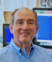 Philip C. Efthimion合作论文数Princeton Plasma Physics Laboratory, Princeton University16
 A. Ramsey合作论文数Plasma Physics Laboratory, Princeton University16
 Kenneth Wayne Hill合作论文数15
 Michael C. Zarnstorff合作论文数Princeton Plasma Physics Laboratory, Princeton University15Silvestar Sesnic合作论文数14H. Hsuan合作论文数14
 Robert Budny合作论文数Plasma Physics Laboratory, Princeton University14D. McCune合作论文数13H. Park合作论文数13
 Szymon Suckewer合作论文数Department of Mechanical and Aerospace Engineering, Princeton University13m ulrickson合作论文数12J. Schivell合作论文数12S. Kaye合作论文数12Dk Owens合作论文数12S. Medley合作论文数12
 H. F. Dylla合作论文数LIGO Laboratory, Massachusetts Institute of Technology11
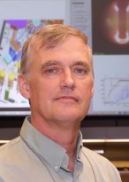 Eric Fredrickson合作论文数Princeton Plasma Physics Laboratory11George Vayakis合作论文数ITER Organization11
 Samuel A. Cohen合作论文数Princeton Program in Plasma Physics, Princeton University11Einar Hinnov合作论文数11D. M. Manos合作论文数Plasma Physics Laboratory, Princeton University11
 Jc Hosea合作论文数10GL SCHMIDT合作论文数10S. Davis合作论文数10David Mikkelsen合作论文数10
 Benoit LeBlanc合作论文数Princeton Plasma Physics Lab10F. Stauffer合作论文数10
 George J. Strachan合作论文数Princeton Plasma Physics Laboratory;Princeton University;Princeton Plasma Physics Laboratory, Princeton University10C.S. Pitcher合作论文数CFFTP, Toronto, Canada10
 Ned Sauthoff合作论文数Princeton Plasma Physics Laboratory, Princeton, NJ 08544, USA10LR GRISHAM合作论文数10G. Schmidt合作论文数9
 Stanley Kaye合作论文数Princeton Plasma Physics Laboratory9Edoardo Mazzucato合作论文数Princeton Plasma Physics Laboratory9




