The main characteristics of toroidal Alfvén eigenmodes (TAEs) have been successfully investigated in JET (Joint European Torus) using the scheme of sweeping-frequency external excitation with tracking of the synchronously-detected resonances. However, due to technical limitations, only modes with low values of the toroidal mode number n ⩽ 7 could be effectively excited and unambiguously identified by the Alfvén Eigenmode Active Diagnostic (AEAD) system. This represents a serious restriction because theoretical models indicate that medium- n Alfvén eigenmodes (AEs) are the most prone to be destabilized by energetic particles in ignited plasmas and, therefore, reliable measurement of their damping rates remains a relevant issue to properly access their effect in ignited plasmas. For this reason, a major upgrade of the AEAD system has been carried out aiming at providing a state-of-the-art excitation and real-time detection system for the planned DT campaign in JET. This required the development of a new type of radio frequency amplifier and filter, not commercially available, and also a control system. In this paper, details of the concepts that are relevant to understand the operation of the new system in the next experimental campaigns are presented, as are the results of numerical simulations to model its performance.
This chapter demonstrates how cold crucible melting, basalt glass melt pour directly from a solid into a container, and sealing of crystalline rock boreholes. Phase transitions and flow from the heating beam can be seen in the thermal emission detected by the radiometer. The new capabilities for non-contact rates of heating, high temperatures, localization, and real-time diagnostic access open up new possibilities for researching and processing glass materials. The energy deposited by a directed energy MMW beam will be spatially localized to a size cross section depending on the frequency used, the size of the waveguide launch aperture, the propagating mode, and the distance to the target surface. The effective maximum power to the samples was limited to about 5 kW by the transmission line system, which included a reflected power isolator to prevent sample surface reflections from interfering with gyrotron operation. The depth of the melt was limited by the high viscosity of granite melt, which limits the flow into the gaps between the fragments and by the limited penetration depth of the MMW beam into the melted granite.
The fast ion and alpha-particle diagnostic is based on collective Thomson scattering of high power 140 GHz radiation.The main aim of the system will be the determination of the spatially resolved velocity distribution of fast ion populationsin JET plasmas, by measuring the frequency spectrum of scattered radiation. A spatial profile of the velocity distribution,with resolution <10 cm, can be determined by scanning the scattering volume (the overlap of the antenna patterns of thelaunch and receive antennas) over the plasma, using steerable launch and receive mirrors. The diagnostic will be used tomeasure fast ion populations produced by the heating systems, and will be particularly important in the tritium phase ofJET when, by a measurement of the velocity distribution of alpha particles created by fusion reactions, the efficiency ofalpha particle heating can be established. It is expected that their velocity distribution can be determined between 0.5MeV (limited because at low frequency shift the spectrum is dominated by the thermal ion feature) and their birth energy(3.5 MeV) with a typical time resolution of 0.1 s. The principal components of the diagnostic are shown schematically infigure 1. They are: a high power long pulse gyrotron and associated equipment, a heterodyne receiver system andtransmission lines. The RF transmission and the receiver system are described in accompanying papers1,2. The physicsprinciples of the diagnostic are described elsewheree.g. 3'4.
We report measurements of the turbulent evolution of the plasma density profile following the fast injection of lithium pellets into the Levitated Dipole Experiment (LDX) [Boxer et al., Nat. Phys. 6, 207 (2010)]. As the pellet passes through the plasma, it provides a significant internal particle source and allows investigation of density profile evolution, turbulent relaxation, and turbulent fluctuations. The total electron number within the dipole plasma torus increases by more than a factor of three, and the central density increases by more than a factor of five. During these large changes in density, the shape of the density profile is nearly “stationary” such that the gradient of the particle number within tubes of equal magnetic flux vanishes. In comparison to the usual case, when the particle source is neutral gas at the plasma edge, the internal source from the pellet causes the toroidal phase velocity of the fluctuations to reverse and changes the average particle flux at the plasma edge. An edge particle source creates an inward turbulent pinch, but an internal particle source increases the outward turbulent particle flux. Statistical properties of the turbulence are measured by multiple microwave interferometers and by an array of probes at the edge. The spatial structures of the largest amplitude modes have long radial and toroidal wavelengths. Estimates of the local and toroidally averaged turbulent particle flux show intermittency and a non-Gaussian probability distribution function. The measured fluctuations, both before and during pellet injection, have frequency and wavenumber dispersion consistent with theoretical expectations for interchange and entropy modes excited within a dipole plasma torus having warm electrons and cool ions.
Description for Zenodo Data Set DOI:10.5281/zenodo.220992 This dataset accompanies the article, to appear in Physics of Plasmas, titled "Turbulent Fluctuations During Pellet Injection into a Dipole Confined Plasma Torus," by Garnier, Mauel, Roberts, Kesner, and Woskov. --------------------------------------------- Data is presented as HDF5 datafiles(see https://www.hdfgroup.org/HDF5/)as HDF4 datafiles(see https://www.hdfgroup.org/release4/doc/index.html)and as CSV datafiles(see http://www.digitalpreservation.gov/formats/fdd/fdd000323.shtml). Data files are associated with FIGURES 2, 3, 4, 5 Data plotted in other figures are derived from the dataset as describedin the paper. ---------------------------------------------start of figure list---------------------------------------------FIGURE 1: No data set ---------------------------------------------FIGURE 2: (HDF4 Files) Four-channel Microwave (60 GHz) InterferometerS140529016_DensityData.hdftime range: 5.00 sec - 7.00 sectime sample: 8 micro-secsamples: 250,000 x 4 channels + 250,000 (total)Unit: radian "Interferometer"Unit: 1.0E18 particles "Total-Particles" 16-channel Photodiode Array 1S140529016_PDAData.hdftime range: 5.00 sec - 7.00 sectime sample: 20 micro-secsamples: 100,000 x 16 channelsUnit: A.U. "PDA-1" TOTAL ECRH Injected Heating PowerS140529016_ECRHData.hdftime range: 5.00 sec - 7.00 sectime sample: 20 micro-secsamples: 100,000Unit: kW "Microwave-Power" S140529016_LoopVoltage.hdftime range: 5.00 sec - 7.00 sectime sample: 80 micro-secsamples: 25,000Unit: milli-Volt x sec "Loop-Voltage" ---------------------------------------------FIGURE 3(a): (HDF4 Files) Four-channel Microwave (60 GHz) InterferometerS140529016_DensityData.hdftime range: 5.00 sec - 7.00 sectime sample: 8 micro-secsamples: 250,000 x 4 channels + 250,000 (total)Unit: radian "Interferometer"Unit: 1.0E18 particles "Total-Particles" 16-channel Photodiode Array 1S140529016_PDAData.hdftime range: 5.00 sec - 7.00 sectime sample: 20 micro-secsamples: 100,000 x 16 channelsUnit: A.U. "PDA-1" ---------------------------------------------FIGURE 4 (a), (b), (c), (d), (e), (f): (CSV Files) time period: 5.0 - 6.0 secEnsemble Window: 8 msecsample period: 8 micro-secNyquist Freq: 62.475 kHz (a) Fig4a-Line-Density-Coherence.csvFrequency (Hz) Hzd(nl-1)^2 dimensionlessd(nl-2)^2 dimensionlessd(nl-3)^2 dimensionlessd(nl-4)^2 dimensionlessLambda 1-2 dimensionlessLambda 1-3 dimensionlessLambda 1-4 dimensionless (b) Fig4b-Isat-Coherence.csvFrequency (Hz) Hzd(I)^2 dimensionlessLambda 8deg dimensionlessLambda 16deg dimensionlessLambda 24deg dimensionless (c) Fig4c-Float-Potential-Coherence.csvFrequency (Hz) Hzd(Pot)^2/Te^ dimensionlessLambda 8deg dimensionlessLambda 16deg dimensionlessLambda 24deg dimensionless (d) Fig4d-Line-Density-Coherence.csvFrequency (Hz) Hzd(nl-1)^2 dimensionlessd(nl-2)^2 dimensionlessd(nl-3)^2 dimensionlessd(nl-4)^2 dimensionlessLambda 1-2 dimensionlessLambda 1-3 dimensionlessLambda 1-4 dimensionless (e) Fig4e-Isat-Coherence.csvFrequency (Hz) Hzd(I)^2 dimensionlessLambda 8deg dimensionlessLambda 16deg dimensionlessLambda 24deg dimensionless (f) Fig4f-Float-Potential-Coherence.csvFrequency (Hz) Hzd(Pot)^2/Te^ dimensionlessLambda 8deg dimensionlessLambda 16deg dimensionlessLambda 24deg dimensionless ---------------------------------------------FIGURE 5 (a), (b): (CSV Files) Figure 5(a)time period: 5.0 - 6.0 secEnsemble Window: 8 msecsample period: 8 micro-secNyquist Freq: 62.475 kHz (a) Fig5a-Float-Isat-CrossPhase.csvFrequency (Hz) Hzalpha-Float degreealpha-Isat degree Figure 5(b)time period: 6.02 - 6.05 secEnsemble Window: 1.6 msecsample period: 8 micro-secNyquist Freq: 62.475 kHz (b) Fig5b-Float-Isat-DuringCrossPhase.csvFrequency (Hz) Hzalpha-Float degreealpha-Isat degreekappa-Float dimensionlesskappa-Isat dimensionless---------------------------------------------FIGURE 6: No data set ---------------------------------------------FIGURE 7: No data set ---------------------------------------------FIGURE 8: No data set ---------------------------------------------FIGURE 9: No data set ---------------------------------------------FIGURE 10: No data set ---------------------------------------------end of figure list------------------------------------------------------------------------------------------start of file list---------------------------------------------Filename Size----------------------------------------------All-Probe-Data.h5 9.8 MBAverage-Isat-Data.h5 422 KBAverage-Probe-Data.h5 1.1 MBFig4a-Line-Density-Coherence.csv 413 KBFig4b-Isat-Coherence.csv 251 KBFig4c-Float-Potential-Coherence.csv 250 KBFig4d-Line-Density-Coherence.csv 103 KBFig4e-Isat-Coherence.csv 62 KBFig4f-Float-Potential-Coherence.csv 62 KBFig5a-Float-Isat-CrossPhase.csv 138 KBFig5b-Float-Isat-DuringCrossPhase.csv 36 KBPotential-Time-Angle-Data.h5 255 KBS140529016_DensityData.hdf 6 MBS140529016_ECRHData.hdf 803 KBS140529016_LoopVoltage.hdf 203 KBS140529016_PDAData.hdf 6.8 MBLDX-Pellet-Supplementary.pdf 1.8 MBS140529016_frPlots.mp4 3.2 MB---------------------------------------------end of file list---------------------------------------------
Short-wavelength, low-frequency, frequently coherent fluctuations regulate transport across the plasma boundary in all steady-state tokamak confinement regimes of interest for a reactor. In the ideal case, these fluctuations expel particles, especially impurities, without significantly degrading energy confinement. The Shoelace antenna is a novel tool employed on the Alcator C-Mod tokamak designed to couple to such fluctuations inductively.The antenna is a ladder-like structure, constructed of lanthanum-doped molybdenum wire rungs wound around alumina tension wheels. There are 19 rungs approximately 15 cm long and 2 cm apart. Adjacent rungs carry equal and opposite currents over a range of frequencies from 50-300 kHz. These parameters are selected to match two frequently-occurring fluctuations: the Quasi-Coherent Mode (QCM) and the Weakly Coherent Mode (WCM). The antenna must withstand high heat flux and large JxB forces due to its proximity to the plasma.The outputs of two commercial broadband RF amplifiers are combined with transformers to drive the antenna. An agile tuning and matching network, consisting of 80 series and 80 parallel capacitors with fast solid-state RF switches, can couple up to 8 kW of power to the antenna over the entire operational band. The frequency input to the amplifiers can be swept to hunt for an appropriate mode, and then a phase lock loop can take over to track the plasma fluctuation signal in real-time.Initial operation of the antenna indicated a weakly-damped resonant plasma response centered at the QCM frequency, a result which suggests that the antenna-induced fluctuation may drive beneficial transport across the plasma edge.
A wide-frequency range (50-300 kHz) power system has been implemented for use with a new RF antenna - the "Shoelace" antenna - built to drive coherent plasma fluctuations in the edge of the Alcator C-Mod tokamak. A custom, dynamically tunable matching network allows two commercial 1 kW, 50-Ω RF amplifiers to drive the low-impedance, inductive load presented by the antenna. This is accomplished by a discretely variable L-match network, with 81 independently selected steps available for each of the series and parallel legs of the matching configuration. A compact programmable logic device provides a control system that measures the frequency with better than 1 kHz accuracy and transitions to the correct tuning state in less than 1 ms. At least 85% of source power is dissipated in the antenna across the operational frequency range, with a minimum frequency slew rate of 1 MHz/s; the best performance is achieved in the narrower band from 80 to 150 kHz which is of interest in typical experiments. The RF frequency can be run with open-loop control, following a pre-programmed analog waveform, or phase-locked to track a plasma fluctuation diagnostic signal in real time with programmable phase delay; the amplitude control is always open-loop. The control waveforms and phase delay are programmed remotely. These tools have enabled first-of-a-kind measurements of the tokamak edge plasma system response in the frequency range and at the wave number at which coherent fluctuations regulate heat and particle transport through the plasma boundary.
Conventional drilling methods are very mature, but still have difficulty drilling through very deep,very hard and hot rocks for geothermal, nuclear waste entombment and oil and gas applications.This project demonstrated the capabilities of utilizing only high energy beams to drill such rocks,commonly called 'Direct Energy Drilling', which has been the dream of industry since the invention of the laser in the 1960s. A new region of the electromagnetic spectrum, millimeter wave (MMW) wavelengths at 30-300 giga-hertz (GHz) frequency was used to accomplish this feat. To demonstrate MMW beam drilling capabilities a lab bench waveguide delivery, monitoring and instrument system was designed, built and tested around an existing (but non-optimal) 28 GHz frequency, 10 kilowatt (kW) gyrotron. Low waveguide efficiency, plasma generation and reflected power challenges were overcome. Real-time monitoring of the drilling process was also demonstrated. Then the technical capability of using only high power intense millimeter waves to melt (with some vaporization) four different rock types (granite, basalt, sandstone, limestone) was demonstrated through 36 bench tests. Full bore drilling up to 2" diameter (size limited by the available MMW power) was demonstrated through granite and basalt samples. The project also demonstrated that MMW beam transmission losses through high temperature (260°C, 500oF), high pressure (34.5 MPa, 5000 psi) nitrogen gas was below the error range of the meter long path length test equipment and instruments utilized. To refine those transmission losses closer, to allow extrapolation to very great distances, will require a new test cell design and higher sensitivity instruments. All rock samples subjected to high peak temperature by MMW beams developed fractures due to thermal stresses, although the peak temperature was thermodynamically limited by radiative losses. Therefore, this limited drill rate and rock strength data were not able to be determined experimentally. New methods to encapsulate larger rock specimens must be developed and higher power intensities are needed to overcome these limitations. It was demonstrated that rock properties are affected (weakening then strengthened) by exposure to high temperatures. Since only MMW beams can economically reach rock temperatures of over 1650°C, even exceeding 3000°C, that can cause low viscosity melts or vaporization of rocks. Future encapsulated rock specimens must provide sufficiently large sizes of thermally impacted material to provide for the necessary rock strength, permeability and other analyzes required. Multiple MMW field systems, tools and methods for drilling and lining were identified. It was concluded that forcing a managed over-pressure drilling operation would overcome water influx and hot rock particulates handling problems, while simultaneously forming the conditions necessary to create a strong, sealing rock melt liner. Materials that contact hot rock surfaces were identified for further study. High power windows and gases for beam transmission under high pressures are critical paths for some of the MMW drilling systems. Straightness/ alignment can be a great benefit or a problem, especially if a MMW beam is transmitted through an existing, conventionally drilled bore.
A wide-frequency range (50-300 kHz) power system has been implemented for use with a new RF antenna – the “Shoelace” antenna – built to drive coherent plasma fluctuations in the edge of the Alcator C-Mod tokamak. A custom, dynamically-tunable matching network allows two commercial 1 kW, 50-Ω RF amplifiers to drive the low-impedance, inductive load presented by the antenna. This is accomplished by a discretely-variable L-match network, with 81 independentlyselected steps available for each of the series and parallel legs of the matching configuration. A compact programmable logic device (CPLD) provides a control system that measures the frequency with better than 1 kHz accuracy and transitions to the correct tuning state in less than 1 ms. At least 85% of source power is dissipated in the antenna across the operational frequency range, with a minimum frequency slew rate of 1 MHz/s; the best performance is achieved in the narrower band from 80-150 kHz which is of interest in typical experiments. The RF frequency can be run with open-loop control, following a preprogrammed analog waveform, or phase-locked to track a plasma fluctuation diagnostic signal in real time with programmable phase delay; the amplitude control is always open-loop. The control waveforms and phase delay are programmed remotely. These tools have enabled first-of-a-kind measurements of the tokamak edge plasma system response in the frequency range and at the wave number at which coherent fluctuations regulate heat and particle transport through the plasma boundary.
An efficient reflected power isolator has been built for a 10 kW, 28 GHz gyrotron for operation with a circularly polarized beam. It makes use of a one-dimensional copper grill linear polarizer in a 4-port waveguide cross and a grooved mirror in a miter bend for transformations between linear and circular polarizations. The polarizers are implemented in 76 mm diameter corrugated aluminum waveguide with water loads for power rejection. Backward power isolation of 25 dB and an insertion loss of ~0.3 dB have been determined.
A dual 137 GHz heterodyne radiometer system was used to study grooved nuclear grade graphite (SGL Group NBG17) inside an electric furnace from room temperature to 1250°C. The millimeter wave radiometer views were collinear with the electric field of one polarized parallel, and the other perpendicular, to the grooves. The anisotropic emissivity was readily detected for 100 μm wide grooves of various depths with a spacing period of 0.76 mm. The emissivity in the 500 – 1250°C temperature range was found to be 5.1 ± 0.5% when the E-field was parallel to the grooves and a factor of 2 – 4 higher, depending on groove depth, in the perpendicular direction. The parallel surface emissivity which was identical to ungrooved surface emissivity corresponded to a 137 GHz surface resistance of 5.3 Ohms, which is about 2.5 times higher than the value predicted from frequency scaling dc surface resistance. The perpendicular emissivity had a modulation with groove depth at odd integral multiples of ¼λ, predicted by electromagnetic finite difference time domain analysis.
We describe the design and implementation of the instrumentation required to perform DNP-NMR at higher field strengths than previously demonstrated, and report the first magic-angle spinning (MAS) DNP-NMR experiments performed at (1)H/e(-) frequencies of 700 MHz/460 GHz. The extension of DNP-NMR to 16.4 T has required the development of probe technology, cryogenics, gyrotrons, and microwave transmission lines. The probe contains a 460 GHz microwave channel, with corrugated waveguide, tapers, and miter-bends that couple microwave power to the sample. Experimental efficiency is increased by a cryogenic exchange system for 3.2 mm rotors within the 89 mm bore. Sample temperatures ≤85 K, resulting in improved DNP enhancements, are achieved by a novel heat exchanger design, stainless steel and brass vacuum jacketed transfer lines, and a bronze probe dewar. In addition, the heat exchanger is preceded with a nitrogen drying and generation system in series with a pre-cooling refrigerator. This reduces liquid nitrogen usage from >700 l per day to <200 l per day and allows for continuous (>7 days) cryogenic spinning without detrimental frost or ice formation. Initial enhancements, ε=-40, and a strong microwave power dependence suggests the possibility for considerable improvement. Finally, two-dimensional spectra of a model system demonstrate that the higher field provides excellent resolution, even in a glassy, cryoprotecting matrix.
The goals of this experiment are to determine (a) the sensitivity of Shoelace coupling to EDA H-mode discharges with respect to plasma parameters, particularly q95 and triangularity, (b) the ability of the Shoelace antenna to induce a transition to EDA H-mode or to prolong an intrinsic QCM in parameter space where it does not normally exist, and (c) the e ect of Shoelace antenna operation on global plasma parameters, and particularly transport.
Millimeter-wave (MMW) technologies can provide unique heating and diagnostic capabilities to research the thermal dynamics of materials to extreme temperatures. The MMW properties of rocks in the molten state up to their vaporization temperatures are not well known. Using a 28 GHz gyrotron beam collinear with a 130 GHz radiometry view in a calorimetric chamber, the transitions of granite rock specimens through solid phases, melting, and vaporization were observed, including release of trapped trace gas (<0.07%). The 28 GHz emissivity of molten granite was observed to be approximately constant at 0.66 ± 0.03 up to vaporization where it increased to 0.70 ± 0.03 at an equilibrated temperature of 2710 ± 120°C. An analysis of the thermal power balance during a 76 s steady state vaporization time period indicates that the MMW emissivity of the molten granite is larger than in the infrared. The observations support the possibility that MMW thermal ablative penetration into hot crystalline rock formations could be a more practical approach than infrared laser drilling to access deep resources.
 Henrik Bindslev合作论文数60Søren Bang Korsholm合作论文数42
 Fabrizio Meo合作论文数National Laboratory38
 Jay Kesner合作论文数Plasma Science and Fusion Center;Massachusetts Institute of Technology;Plasma Science and Fusion Center, Massachusetts Institute of Technology37Poul Michelsen合作论文数32
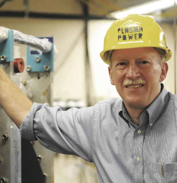 Michael E. Mauel合作论文数Department of Applied Physics and Applied Mathematics, Columbia University31
 Richard Temkin合作论文数Department of Physics, Massachusetts Institute of Technology;Plasma Science & Fusion Center, Massachusetts Institute of Technology31j s machuzak合作论文数30
 Darren T. Garnier合作论文数30Nielsen S. K.合作论文数29
 Erekle Tsakadze合作论文数27Daniel R. Cohn合作论文数25
 Egbert Westerhof合作论文数Trilateral Euregio Cluster24J. A. Hoekzema合作论文数23
 S.K. Sundaram合作论文数Inamori School of Engineering, Alfred University21
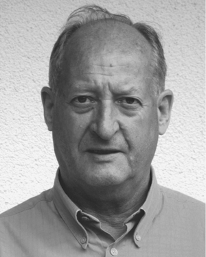 F. Leuterer合作论文数21d y rhee合作论文数20Frank Leipold合作论文数19s michelsen合作论文数17
 Michael A. Shapiro合作论文数Plasma Science and Fusion Center, Massachusetts Institute of Technology15
 Robert Guy Griffin合作论文数Francis Bitter Magnet Lab, Department of Chemistry, Massachusetts Institute of Technology15
 Laurie Porte合作论文数15Jennifer Ellsworth合作论文数Plasma Science and Fusion Center;Massachusetts Institute of Technology;Plasma Science and Fusion Center, Massachusetts Institute of Technology14
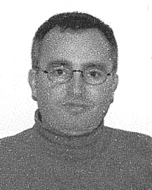 Kamal Hadidi合作论文数Plasma Science and Fusion Center;Massachusetts Institute of Technology13Norton L Bretz合作论文数13K. Hadidi合作论文数12Jan Egedal合作论文数Massachusetts Institute of Technology;Science and Fusion Center12
 Philip C. Michael合作论文数Plasma Science & Fusion Center, Massachusetts Institute of Technology12Paul Thomas合作论文数11H. Oosterbeek合作论文数11Vesna Furtula合作论文数10
 Jagadishwar R. Sirigiri合作论文数Plasma Science and Fusion Center, Massachusetts Institute of Technology10
 Mirko Salewski合作论文数Association Euratom-Risø National Laboratory for Sustainable Energy, Technical University of Denmark10
 Miklos Porkolab合作论文数Department of Physics, Massachusetts Institute of Technology;Plasma Science and Fusion Center, Massachusetts Institute of Technology10
 Philip C. Efthimion合作论文数Princeton Plasma Physics Laboratory, Princeton University9
 Jeremy Stober合作论文数9
 Emilio Alessandro Nanni合作论文数SLAC National Accelerator Laboratory, Stanford University9
 D. Wagner合作论文数9charles h titus合作论文数8J. Machuzak合作论文数8We Daniel合作论文数8Edoardo Mazzucato合作论文数Princeton Plasma Physics Laboratory8G. J. Flores合作论文数8
 Seong-Tae Han合作论文数8
 Robert Budny合作论文数Plasma Physics Laboratory, Princeton University8
 Jc Hosea合作论文数7Alexander Barnes合作论文数Department of Chemistry and Applied Biosciences, Eidgenössische Technische Hochschule Zürich7
 Brian LaBombard合作论文数Plasma Science and Fusion Center, Massachusetts Institute of Technology7K. Young合作论文数7




