This document outlines a community-driven Design Study for a 10 TeV pCM Wakefield Accelerator Collider. The 2020 ESPP Report emphasized the need for Advanced Accelerator R&D, and the 2023 P5 Report calls for the “delivery of an end-to-end design concept, including cost scales, with self-consistent parameters throughout." This Design Study leverages recent experimental and theoretical progress resulting from a global R&D program in order to deliver a unified, 10 TeV Wakefield Collider concept. Wakefield Accelerators provide ultra-high accelerating gradients which enables an upgrade path that will extend the reach of Linear Colliders beyond the electroweak scale. Here, we describe the organization of the Design Study including timeline and deliverables, and we detail the requirements and challenges on the path to a 10 TeV Wakefield Collider.
Fourth-generation storage rings enabled by multi-bend achromat lattices are being inaugurated worldwide and many more are planned for the next decade. These sources deliver stable ultra-high brightness radiation with unmatched levels of transverse coherence by virtue of their highly advanced magnetic lattices. Optimization of these challenging and strongly nonlinear lattices with many degrees of freedom bounded by extensive sets of constraints and multiple often conflicting optimization goals is highly demanding and requires application of the most advanced numerical tools available to the community. While multi-objective genetic algorithms have been very successful in supporting these optimization efforts, the algorithms suffer from a fundamental limitation of their stochastic nature: an exceedingly vast number of candidate lattices, most of which eventually are rejected, has to be fully evaluated. This comes at immense computational cost and thus drives excessive runtime despite use of large supercomputing clusters. We therefore propose to employ deep learning techniques and iterative retraining of neural networks to massively accelerate such lattice evaluation, thereby allowing lattice optimization to rely on far fewer a priori assumptions, open up to larger search ranges, and include right from the start and in parallel multiple error distributions to find truly global optima, all while completing a full optimization campaign in weeks rather than months. In this paper we present the neural network designs, the deep learning approach, iterative retraining procedures, and demonstrate how these machine learning techniques can be incorporated into existing state-of-the-art optimization workflows with only minimal changes applied to the optimization pipeline itself and none at all to the employed tracking codes.
Following the spectacular success of the third-generation light source over the past decades, a few new-generation light sources based on the multibend achromat (MBA) scheme have come into operation. Other such facilities are also under construction while existing ones are being upgraded. Likewise, the Swiss Light Source, which has been in operation for more than 20 years at the Paul Scherrer Institute, is to be upgraded with the present storage ring being replaced by an MBA low-emittance ring. A natural emittance of 158 pm at a beam energy of 2.7 GeV is achieved for a storage ring of comparatively short circumference, 288 m, providing a gross straight section of 83.6 m. The objectives of the upgrade were met under tight constraints by the application of two novel concepts: the introduction of both a longitudinal gradient and a reverse bend into the unit cell and pushing the superperiodicity to the number of arcs, effectively with ``pseudosymmetry.'' A detailed account of the MBA design and its expected performance is presented and the experience gained is highlighted with the aim to facilitate next-generation light source lattice design.
At the Advanced Light Source Upgrade (ALS-U), an onaxis swap-out injection will be used to replenish depleted bunches in the storage ring with refreshed bunches from a full energy accumulator ring. To fulfill this injection process, two transfer lines are required between the storage ring and the accumulator ring: the accumulator-to-storagering (ATS) transfer line and the storage-ring-to-accumulator (STA) transfer line. The design of the ATS/STA transfer lines is a challenging task as they must fit within a tight injection region while also accommodating the storage and accumulator rings at different elevations. Moreover, the ATS/STA design needs to meet both the boundary conditions and optics requirements. In this paper, we will present a design of the ATS/STA transfer lines.
As part of the ALS-U design, bunches with small charge will be added to the accumulator ring in a manner that initially leaves both the stored and injected bunches displaced from the nominal orbit. While the beam current is below instability thresholds, transient effects due to the combination of short-range wake fields and large initial displacements can have an impact on injection efficiency. In this paper, the impact of wake fields on the two bunches is detailed using the elegant simulation code, and different techniques to optimize the injection efficiency are explored. INJECTION INTO ALS-U ACCUMULATOR RING The ALS-U is an upgrade of the Advanced Light Source (ALS) to produce diffraction-limited radiation in the soft x-ray regime [1]. The storage ring will swap out single trains of 25 or 26 bunches at a rate of up to once every 30 seconds. The bunch trains will be prepared in a second ring, the accumulator ring (AR), which will itself be fed from the current Advanced Light Source booster in a topoff configuration. The high emittance of the bunches from the booster, combined with the smaller aperture of the AR vacuum chamber compared to the ALS, prevents returning the stored bunch to the reference orbit immediately after injection without significant injection losses. The injection scheme, referred to as 3DK [2], utilizes two pre-injection kickers which only interact with the stored bunch, followed by injection of the bunch from the booster using a pair of septa, and then a third kicker (referred to simply as the "injection kicker") which simultaneously affects both the injected and stored bunches. This configuration allows for a large separation between the kickers, and offers a wide range of flexibility in terms of the final disposition of the two bunches. A direct optimization of the injection efficiency leads to settings which give the stored bunch a significantly higher transverse excitation after the injection kicker than the injected bunch; this will be referred to as Mode A. These settings are driven by the larger emittance of the injected bunches and the narrow apertures in the AR (compared with the current ALS apertures). The maximum trajectory offset of the injected bunch is in fact slightly smaller than its rms width. The stored bunch, on the other hand, will have already equilibrated to a much smaller emittance and can be ∗ This work was supported by the Director, Office of Science, Office of Basic Energy Sciences, of the U.S. Department of Energy under Contract No. DE-AC02-05CH11231. † gepenn@lbl.gov pushed closer to the walls of the vacuum chamber without incurring losses. Through single-particle tracking, Mode A is found to incur negligible losses for the stored bunch, and significantly less than 1% losses for the injected bunch. SHORT-RANGE WAKES This picture changes when short-range transverse wake fields are taken into account. The wake fields are well below the level of generating a transverse head-tail instability, with a threshold of 5.8 nC bunch charge compared to the nominal bunch charger of 1.15 nC. However, the injected bunch occupies most of the physical aperture of the vacuum chamber until the bunch becomes damped, and thus transient wakes can cause significant injection losses even in the absence of an instability. The injected bunch carries only 10% of the nominal charge, so the intensity of the wakes is determined by the trajectory offset of the stored bunch. The transverse short-range wake potentials have been calculated based on detailed models of each beamline element, and the combined total is shown in Fig. 1. These are obtained as a pseudo-Green’s function [3] through simulating a comparatively short 1-mm bunch in the electromagnetic code CST Suite [4]. -10 0 10 20 30 40 50 60 -10 0 10 20 30 40 50 W e ig h te d p o te n ti a l β ·W ( k V /p C ) s (mm) Horizontal Vertical Total transverse wakes Figure 1: Transverse short-range wake field potentials for the ALS-U accumulator ring. Simulations using the code elegant [5] show that wake fields prevent the stored bunch from completely decohering in phase, as seen in Fig. 2. The evolution of the bunches is shown in Fig. 3. Note that in the presence of wakes, the stored bunch does not grow as large as it does without wakes, and there is also a larger oscillation amplitude after around 2000 turns around the ring. Meanwhile, the injected bunch with wakes incurs a significant increase in both bunch width and displacement, peaking after 1500 turns (about 1 ms). Increased losses also occur about this time. There are modulations in the envelope of the centroid motion after this, but overall it takes many milliseconds for the transverse motion to damp out. 12th Int. Particle Acc. Conf. IPAC2021, Campinas, SP, Brazil JACoW Publishing ISBN: 978-3-95450-214-1 ISSN: 2673-5490 doi:10.18429/JACoW-IPAC2021-MOPAB118 MC2: Photon Sources and Electron Accelerators A05 Synchrotron Radiation Facilities MOPAB118 429 C on te nt fr om th is w or k m ay be us ed un de rt he te rm s of th e C C B Y 3. 0 lic en ce (© 20 21 ). A ny di st ri bu tio n of th is w or k m us tm ai nt ai n at tr ib ut io n to th e au th or (s ), tit le of th e w or k, pu bl is he r, an d D O I
Author(s): Ehrlichman, M; Hellert, T; Leemann, SC; Penn, G; Steier, C; Sun, C; Venturini, M; Wang, D | Abstract: The ALS-U light source will implement on-axis single-train swap-out injection employing an accumulator between the booster and storage rings. The accumulator ring design is a twelve period triple-bend achromat that will be installed along the inner circumference of the storage-ring tunnel. A non-conventional injection scheme will be utilized for top-off off-axis injection from the booster into the accumulator ring meant to accommodate a large $\sim 300$~nm emittance beam into a vacuum-chamber with a limiting horizontal aperture radius as small as $8$ mm. The scheme incorporates three dipole kickers distributed over three sectors, with two kickers perturbing the stored beam and the third affecting both the stored and the injected beam trajectories. This paper describes this ``3DK'' injection scheme and how it fits the accumulator ring's particular requirements. We describe the design and optimization process, and how we evaluated its fitness as a solution for booster-to-accumulator ring injection.
As the broad-band impedance modeling and vacuumchamber design of the new Advanced Light Source storage ring (ALS-U) are reaching maturity, we report on progress in our single-bunch collective effects studies. A pseudo-Green function wake representing the entire ring was earlier obtained by numerical and analytical methods. Macroparticle simulations using the code elegant based on the pseudoGreen function are used to determine the instability thresholds for longitudinal and transverse beam motion. We consider various operating conditions, such as without/with higher-harmonic RF cavities and zero/finite linear chromaticity. Results show enough margin for the broadband impedance budget when the single-bunch instability thresholds are compared with the design bunch charge. STORAGE RING PARAMETERS The upgrade of the Advanced Light Source (ALS-U) to a diffraction-limited soft x-rays radiation source with brightness about two orders of magnitude higher than in the existing ALS is currently underway at the Lawrence Berkeley National Laboratory (LBNL). The storage-ring parameters are listed in Table 1 [1]. The parameters are for lattice version v20r. The 500 mA average current is distributed evenly among the 284 bunches of the beam, consisting of eleven 25or 26-bunch trains. The harmonic number is h = 328. The design bunch charge, which is more relevant for singlebunch broadband-impedance driven instabilities, is 1.15 nC. Without high-order harmonic cavity (HHC) the natural rms bunch length is 4.5 mm. With HHC the FWHM bunch length is 34 mm. In these simulations the HHC is tuned to induce a flat-top bunch profile. The simulations without HHC are relevant for the commissioning and early-operation phase when the beam current is too low to drive the passive HHC. PSEUDO-GREEN FUNCTIONS The elegant [2] simulations make use of the total pseudoGreen functions shown in Fig. 1. These were obtained with a 1 mm rms length drive beam using the code CST [3] in both the longitudinal and transverse plane. This corresponds to an impedance frequency spectrum cut-off of about 100 GHz, which we believe is adequate to include the spectral range of interest. ∗ This work was supported by the Director, Office of Science, Office of Basic Energy Sciences, of the U.S. Department of Energy under Contract No. DE-AC02-05CH11231. † dwang2@lbl.gov Table 1: ALS-U Storage Ring Parameters Parameters Beam energy, E 2.0 GeV Tune, νx/νy 41.357/20.354 Natural chromaticities, ξx/ξy −65.2 /−64.84 Emittance, εx0 116 pm Energy spread, σδ 11.4×10⁻⁴ Revolution time, 0.67 μs Energy loss/turn, U0 217 keV FWHM bunch length (with HHC), 34 mm Natural rms bunch length (no HHC), 4.5 mm Single bunch charge, 1.15 nC -10 0 10 20 30 40 50 s (mm) -300 -250 -200 -150 -100 -50 0 50 100 150 W z ( V/ pC ) 1mm beam transitons HHC RF cavities BPMs + gate valves flanges RW others total 11 Prepare Pseudo-Green function for bea -dynamics simulation: longitudinal -30 -20 -10 0 10 20 30 s (mm) -1 -0.5 0 0.5 1 y W y ( V/ pC ) 105 1mm beam transitons collimators BPMs + gate valves flanges RW others total -10 0 10 20 30 40 50 s (mm) -300 -250 -200 -150 -100 -50 0 50 100 150 W z ( V/ pC ) 1mm beam transitons HHC RF cavities BPMs + gate valves flanges RW others total 11 Prepare Pseudo-Green function for beam-dynamics simulation: longitudinal -30 -20 -10 0 10 20 30 s (mm) -1 -0.5 0 0.5 1 y W y ( V/ pC ) 105 1mm beam transitons collimators BPMs + gate valves flanges RW others total Figure 1: Longitudinal (top) and vertical (bottom) pseudowake functions for the various sources, as indicated in the in-set, and their total (1 mm long rigid drive bunch). The transverse wake is beta-weighted based on the local betatron-function value at the impedance source. In this paper we only report results for the vertical plane since the weighted transverse impedance in the horizontal plane is somewhat weaker [4]. 12th Int. Particle Acc. Conf. IPAC2021, Campinas, SP, Brazil JACoW Publishing ISBN: 978-3-95450-214-1 ISSN: 2673-5490 doi:10.18429/JACoW-IPAC2021-WEPAB082 MC5: Beam Dynamics and EM Fields D05 Coherent and Incoherent Instabilities Theory, Simulations, Code Developments WEPAB082 2783 C on te nt fr om th is w or k m ay be us ed un de rt he te rm s of th e C C B Y 3. 0 lic en ce (© 20 21 ). A ny di st ri bu tio n of th is w or k m us tm ai nt ai n at tr ib ut io n to th e au th or (s ), tit le of th e w or k, pu bl is he r, an d D O I
For the ALS-U project, particles will be injected from the booster to the accumulator ring utilizing an injection scheme that leaves the stored and injected particles with a non-trivial transient. This transient requires that multibunch feedback be masked for those buckets into which charge is injected. The masking significantly diminishes the damping capability of the multibunch feedback system. This problem is exacerbated by the large injection transient. The higher order multibunch resistive wall wake fields in the accumulator ring exceed the radiation damping time. To study whether the beam will remain multibunch stable during the injection transient, a multibunch tracking simulation is used that simulates the multibunch feedback system and also pseudo-mode representation of resistive wall wake fields.
The Advanced Light Source Upgrade will implement on axis single-train swap-out injection employing an accumulator between the booster and storage rings. The accumulator ring (AR) design is a twelve period triple-bend achromat that will be installed along the inner circumference of the storage-ring tunnel. A nonconventional injection scheme will be utilized for top-off off axis injection from the booster into the AR meant to accommodate a large similar to 300 nm emittance beam into a vacuum-chamber with a limiting horizontal aperture radius as small as 8 mm. The scheme incorporates three dipole kickers distributed over three sectors, with two kickers perturbing the stored beam and the third affecting both the stored and the injected beam trajectories. This paper describes this "3DK" injection scheme and how it fits the AR's particular requirements. We describe the design and optimization process, and how we evaluated its fitness as a solution for booster-to-accumulator ring injection.
The Advanced Light Source (ALS) at Lawrence Berkeley National Laboratory is upgrading the existing storage-ring lattice to a nine-bend-achromat lattice with on-axis swap-out injection. The upgraded storage ring will provide a highly focused beam of about 15 μm transverse rms sizes at IDs, with a single bunch-train energy of about 60 J at 2.0 GeV. Such a small and intense beam could damage the transfer-line vacuum chambers in case of an extraction-element failure or the storage-ring vacuum chamber in case of an RF failure. To mitigate the potential damage, a fast kicker magnet (decoherence kicker) will be installed in the storage ring and activated to dilute the beam charge density either on the train to be swapped out a few 100’s turns before extraction or on the whole beam after an RF failure. In this paper, we present both the physics and engineering designs of this decoherence kicker.
The bare lattice optimization for the linear and nonlinear ALS-U storage ring lattice, even without reverse bending, comprises 11 degrees of freedom (DoF) and is therefore a very complex and highly time-consuming process. This design process relies heavily on multi-objective genetic algorithms (MOGA), usually requiring many months of experienced scientists’ time. The main problem lies in having to evaluate vast numbers of candidate lattices due to the stochastic process of MOGA. Although almost all of these candidates are eventually rejected, they nevertheless require extensive particle tracking to arrive at a Pareto front. We therefore propose a novel Machine Learning (ML) pipeline in which nonlinear tracking is replaced by two well-trained neural networks (NNs) to predict dynamic aperture (DA) and momentum aperture (MA) for any lattice candidate. Initial training of these models takes only several minutes on conventional CPUs while predictions are then rendered near instantaneously. We present this novel method and demonstrate the resulting orders of magnitude speedup of the ML-enhanced MOGA process on a 2-DoF problem as well as first results on a more complex 11-DoF problem.
The Advanced Light Source Upgrade (ALS-U) to a diffraction-limited soft x-rays light source requires the construction of an Accumulator Ring (AR) to enable swap-out, on-axis injection. The AR lattice is a Triple-Bend-Achromat lattice similar to that of the current ALS but to minimize the magnet sizes the vacuum chamber will be significantly narrower hence requiring a careful evaluation of the magnets’ field quality. This work presents the results of a detailed error tolerance study including a complete simulation of the commissioning process.
The Advanced Light Source (ALS) storage ring operates multiple feedbacks and feed-forwards during user operations to ensure that various source properties such as beam position, beam angle, and beam size are maintained constant. Without these active corrections, strong perturbations of the electron beam would result from constantly varying insertion device (ID) gaps and phases. An important part of the ID gap/phase compensation requires recording feed-forward tables. While recording such tables takes a lot of time during dedicated machine shifts, the resulting compensation data is imperfect due to machine drift both during and after recording of the table. Since it is impractical to repeat recording feed-forward tables on a more frequent basis, we have decided to employ Machine Learning techniques to improve ID compensation in order to stabilize electron beam properties at the source points.
The ALS-U project to upgrade the Advanced Light Source to a multi bend achromat lattice received CD-1 approval in 2018 marking the end of its conceptual design phase. The ALS-U design promises to deliver diffraction limited performance in the soft x-ray range by lowering the horizontal emittance to about 70 pm rad resulting in two orders of magnitude brightness increase for soft x-rays compared to the current ALS. The design utilizes a nine bend achromat lattice, with reverse bending magnets and on-axis swap-out injection utilizing an accumulator ring. This paper presents recent design progress of the accelerator, as well as new results of the R&D program.
In order to maintain beam quality during transport through a storage ring, sextupole magnets are used to make chromatic corrections, but necessarily introduce deleterious effects such as nonlinear resonances and reduced dynamic aperture. Implementing intricate sextupole distributions to mitigate these effects will rely on precision beam-based measurement of the applied sextupole distribution. In this work, we generalize previous sextupole mapping techniques by using resonant phase-locked excitation of the beam at the Cornell Electron Storage Ring (CESR) [1], which accounts for variations in the normal mode tunes on a turn by turn basis. The methods presented here are applied to simulation and actual turn by turn (TbT) data in CESR for both simplified and realistic sextupole distributions.
A beam-based technique is applied to determine the quadrupole impedance of large-impedance components of the CESR storage ring. Two bunches separated by 1/3 of the ring circumference are charged to 1.44 x 10(10) and 0.48 x 10(10) N/bunch (0.9 and 0.3 mA). Both bunches are given a single kick of the same amplitude. Turn-by-turn, bunch-by-bunch position information is recorded for 16 k turns. BPM-by-BPM phase is calculated using the All-phase FFT method of spectral analysis. The difference in the BPM-to-BPM phase advance between the two bunches is a measurement of the local transverse impedance. The impedances of a small-aperture in-vacuum undulator, collimators, scrapers, RF cavities, electrostatic separators, and bulk impedance of the remaining ring are determined in this manner.
The longitudinal gradient bend is an effective method for reducing the natural emittance in light sources. It is, however, not a common element. We have analyzed its magnetic field and derived a set of formulae. Based on the derivation, we discuss how to model the longitudinal gradient bend in accelerator codes that are used for designing electron storage rings. Strengths of multipole components can also be evaluated from the formulae, and we investigate the impact of higher order multipole components in a very low emittance lattice.
Fast Ion Instability can lead to deterioration of an electron beam (increasing emittance and instability of a train of bunches) in storage rings and linacs. We study this at the Cornell Electron Storage Ring Test Accelerator using a 2.1 GeV low emittance beam. As the source of ions is residual gas, our measurements are conducted at various pressures, including nominal vacuum as well as injected gas (Ar, Kr). We measure turn-by-turn vertical bunch size and position, as well as the multi-bunch power spectrum. A detailed simulation is then used to compare theory with observations.
A multiobjective genetic algorithm is developed for optimizing nonlinearities in diffraction limited storage rings. This algorithm determines sextupole and octupole strengths for chromaticity correction that deliver optimized dynamic aperture and beam lifetime. The algorithm makes use of dominance constraints to breed desirable properties into the early generations. The momentum aperture is optimized indirectly by constraining the chromatic tune footprint and optimizing the off-energy dynamic aperture. The result is an effective and computationally efficient technique for correcting chromaticity in a storage ring while maintaining optimal dynamic aperture and beam lifetime.
A new storage ring is planned for the upgrade of the Swiss Light Source (SLS). It will replace the 12 triple bend achromats by twelve 7-bend achromats, which are based on low aperture longitudinal gradient bends (LGBs) and anti-bends (ABs), thus reducing the emittance from 5.0 nm to about 150 pm at 2.4 GeV while maintaining the source points of the undulator based beam lines. Sextupole and octupole strengths are determined using a multi-objective genetic algorithm (MOGA) and result in sufficient dynamic aperture for off-axis injection and several hours of Touschek lifetime. Superconducting LGBs of 5-6 T peak field will extend the photon range of the SLS up to 80-100 keV. The vacuum system will be based on a 20 mm inner diameter copper beam pipe with ante-chamber, and discrete getter pumps. It is planned to reuse the existing injector complex and the dynamically adjustable girder system.
 D. Sagan合作论文数Cornell University14Thorsten Hellert合作论文数DESY11j shanks合作论文数10
 Georg Hoffstaetter De Torquat合作论文数Cornell Laboratory for Accelerator-based Sciences and Education, Department of Physics, College of Arts and Sciences, Cornell University9G. Penn合作论文数9
 Christoph Steier合作论文数Accelerator Technology and Applied Physics Division, Lawrence Berkeley National Laboratory9D. Rubin合作论文数8Alexander B Temnykh合作论文数8Simon Leemann合作论文数8W. Hartung合作论文数7Suntao Wang合作论文数7
 Changchun Sun合作论文数Lawrence Berkeley National Laboratory7
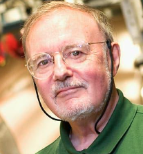 Maury Tigner合作论文数Department of Physics, The College of Arts & Sciences, Cornell University7
 Ivan V. Bazarov合作论文数Department of Physics, College of Arts & Sciences, Cornell University6
 Nicholas L. Rider合作论文数Lancaster General Hospital6
 Matthias Liepe合作论文数Departments of Physics, College of Arts & Sciences, Cornell University6
 Bruce M. Dunham合作论文数Laboratory for Elementary Particle Physics;Cornell University;Lancaster University;Cornell University, Lancaster University6M. Billing合作论文数6
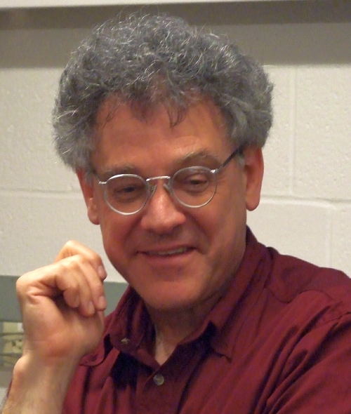 Sol M. Gruner合作论文数Department of Physics, Cornell University6
 Donald H. Bilderback合作论文数Cornell High Energy Synchrotron Source, Cornell University;School of Applied and Engineering Physics, Cornell University6Andreas Streun合作论文数5d peterson合作论文数5
 Dan Wang合作论文数Corresponding author.5
 Avishek Chatterjee合作论文数D Lab, Maastricht Univ5
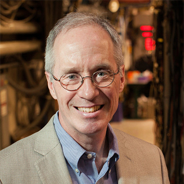 Joel Donald Brock合作论文数School of Applied and Engineering Physics, Cornell University5
 Hasan Padamsee合作论文数5Vadim Veshcherevich合作论文数5D. Peterson合作论文数4E. Fontes合作论文数4Stefano De Santis合作论文数4
 Jared Maxson合作论文数Department of Physics, College of Arts and Sciences, Cornell University4J. Crittenden合作论文数4
 Sergey a Belomestnykh合作论文数Cornell University4J. Shanks合作论文数3n valles合作论文数3M. Aiba合作论文数3R. G. Helmke合作论文数3Philipp Amstutz合作论文数3Christopher Mayes合作论文数3
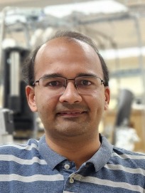 Siddharth Karkare合作论文数Department of Physics, Arizona State University3Dl Hartill合作论文数3r seeley合作论文数3Peter Revesz合作论文数3
 Karl W Smolenski合作论文数Laboratory for Elementary-Particle Physics;Cornell University;Laboratory for Elementary-Particle Physics, Cornell University3John Dobbins合作论文数3Marco Venturini合作论文数3
 Colwyn Gulliford合作论文数IVF Research;Xelera Research3
 L. Cultrera合作论文数University La Sapienza3




