This contribution presents a novel design approach for N-stage low-noise amplifiers (LNAs), with N >= 3, capable of ensuring simultaneous conjugate match, minimum noise measure, prescribed gain (within the technological limits), and minimum inter-stage mismatch (in the Pareto sense) at the design frequency. For reasons of clarity, the illustration of the N = 3 case is carried out at length, whereas the N > 3 case is only briefly described since, except for a change of indices, it is basically identical. The method is a nontrivial extension of a previously presented one, which was limited, however, to two-stage designs. The design method also integrates linearity assessment directly at the draft stage, contrary to previous works. As an example of application, the design of a real-world three-stage LNA operating in Ka-band is presented.
This research focuses on the design and simulation of a V-band single-chip transmit-and-receive front-end integrating an LNA, PA and switching functions for ISL terminals. Two technologies are compared: a 60 nm GaN/Si HEMT from MESC and a 100 nm GaAs HEMT from UMS. In Tx mode, the proposed design targets a saturated output power of at least 20 dBm and a power-added efficiency of no less than 5%. In Rx mode, the goal is 4 dB noise figure. In both cases, the small signal gain must exceed 20 dB across the 59-71 GHz band.
This contribution provides, by means of a simple, applied example, a quick recapitulation of the conversion matrix-related theory behind the stability analysis of electronic circuits under large-signal, periodic excitations. In particular, it is recalled that some level of approximation is inherent to the conversion matrix representation of the circuit as soon as a finite harmonic order is assumed. However, better and better accuracy of the representation (and therefore reliability of the tests based on that) ensues with increasing the harmonic order. On the other hand, it is shown that purposely neglecting the trans-frequential elements of the conversion matrix representation is not justified and leads in general to unreliable results.
This paper presents an ultra-wideband High Power Amplifier (HPA) operating in the 6-18 GHz frequency range. The design approach tackles the challenge of achieving an average output power equal to 10 W under 20-V VDD power supply, with over 24.5 dB power gain and an associated Power Added Efficiency (PAE) of over 28% across the entire operational frequency range. The HPA delivers an average linear gain of 35 dB, outperforming current state-of-the-art solutions. The MMIC HPA has been designed and fabricated using 0.15 mu m AlGaN/GaN HEMT process provided by the UMS foundry.
In a recent paper, it has been shown that, if an N-port network fulfills the condition of (geometrical) unconditional stability at a given frequency, then it can be conjugately matched simultaneous at all ports through lossless matching 2-ports. The proof was based on the construction of a guided iterative algorithm (AlgG) which was shown to converge to the desired result. Two other iterative algorithms were presented (AlgS and AlgA), which are simpler to implement but whose global convergence had not been proven. The present contribution aims at proving the global convergence of the AlgA algorithm, which is notable for being totally independent of the user (unlike AlgG) and of the port numbering (unlike AlgS). As such, this algorithm captures the inherent characteristics only of the network to which it is applied. Several examples of using AlgA to achieve the Simultaneous Conjugate Match (SCM) condition are presented and validated on fabricated circuits. More interestingly, AlgA has a useful role in the framework of stability analysis, i.e., in determining upper and lower bounds on the stability radius of N-port networks. This latter application will be further delved into in a future publication.
This work focuses on designing, fabricating, and testing a broadband low-noise amplifier (LNA) by exploiting dissipative reciprocal matching networks. With reference to a broadband power amplifier, the critical theoretical aspects of the proposed approach have already been presented in a previous publication from the same authors. Herein, the mathematical aspects to extend the applicability of the approach to an LNA are briefly analyzed, and a sample project is discussed in detail. Compared to the cited work, the theoretical impedances needed for the flat-gain condition happen to be more critical in this particular case, imposing the adoption of a more complex base cell, i.e., a cascode pair, and an unconventional output matching network built on a Guanella transformer. The amplifier showed a measured input-output return loss better than 10 dB, a gain of 7.5 +/- 1.5 dB, and a noise figure better than 2.5 +/- 0.5 dB over the subband 4-35 GHz.
In this contribution a first demonstrator of a Low-Noise Amplifier (LNA) employing an Enhancement-mode Gallium Nitride (GaN) High Electron Mobility Transistor in industrial-grade technology is given. The realized demonstrator MMIC features 20 dB gain and 1.5 dB Noise Figure in the 27 to 31 GHz bandwidth, targeting Ka-band SATCOM applications. A depletion-mode GaN LNA is realised in the same foundry run to comparatively assess the advantages and disadvantages of the E- and D-mode GaN LNA solutions. To the best of the Authors' knowledge this is the first example of a MMIC GaN LNA realized using an Enhancement-mode (normally-OFF) transistor.
ABSTRACTA novel, analytical treatment of noise factor in ideal transmission lines subjected to thermal gradients is presented. Temperature dependence on the propagation direction is assumed linear, whereas line loss is initially considered constant. The latter restriction is then removed, in such a manner that, for the first time in the literature, linearly varying line losses are also addressed. In both cases, closed formulae are presented allowing to compute line noise factor for arbitrary source terminations. Previous numerical implementations of the underlying theory are also reappraised both as an introduction to the Reader and as a test bench of the closed‐form results. A discussion of the effects of a non‐uniform temperature distribution across the transverse section of the transmission line is provided upfront, so as to clarify the conditions under which the usual simplifications are valid. This discussion too is believed by the Authors to be original.
The first issue that needs to be addressed when designing a high-frequency amplifier is whether the circuit performance specifications can be met with the selected technology. In case the termination on one of the ports of the active device is fixed, the problem is usually solved using the gain and mismatch limits available in the literature. Otherwise, when the loads at the ports of the active device are not constrained, an analytical criterion is available in the literature to address the problem. However, it is not well known, so it is little exploited. Moreover, a proof of the criterion is not available in the literature. This paper presents a simple geometric proof of the criterion referenced. Closed-form expressions of the terminations determining the fulfilment of the amplifier design goals are determined and the stability of the amplifier in relation to the fulfilment of the performance specifications is addressed. Finally, it is shown that the criterion and the analysis developed in the paper are useful tools for the development of design methodologies of microwave amplifiers operating in more general conditions.
Advanced interconnect technologies are enabling solutions to obtain adequate low-noise amplifier performance even when the circuit is packaged and connected inside a receiver module. In this letter, we present suitable technology and design solutions of a gallium arsenide low-noise amplifier operating in the telecom W-band (92-115 GHz) featuring 20-dB gain and 4.1-dB noise figure accounting for through-the-substrate RF interconnect (hot vias) effects. To the best of the author's knowledge, this is the first low-noise amplifier with hot via interconnections operating up to 115 GHz showing characterized data in terms of noise figure and third-order intermodulation.
This work presents a novel three-stage low-noise amplifier (LNA) design methodology. The first two stages consist of common-source stages with inductive source degeneration, while the third stage consists of an RC network attached before the common-source FET transistor. The input matching network is designed to meet the optimum noise measurement termination, which results in a noise Figure of less than 1.6 dB. The highest gain level of 25 dB was measured, and the input and output reflection coefficients are better than 10 dB for the operating bandwidth, i.e., 13–15 GHz. The LNA’s large signal performance and robustness against continuous high input power and pulse waves are reported. This LNA can handle up to 15 dBm input pulse of 50 nS width and 10% duty cycle, and 18 dBm continuous wave without noticing an increment in the forward gate current.
Recent Earth Observation (EO) missions like SMOS (for Soil Moisture and Ocean Salinity) have revealed that Radio Frequency Interference (RFI) sources in L-band are widespread on the surface of the Earth and can affect the scientific return of future missions. If the RFI signals are strong enough they can also cause irreversible damage to the onboard instrumentation. To prevent this, we need front-end receivers and, consequently, first-stage low noise amplifiers (LNAs) that are robust against damage from strong RFI. This paper presents the design and test results of a robust L-band MMIC LNA operating from 0.4 to 2 GHz and using a space-qualified 150 nm GaN-on-SiC semiconductor process. The LNA employs a cascode architecture and achieves a small-signal gain of 20 dB with a worst-case noise figure of $1.25 \text{dB}$. The LNA was tested for robustness against strong RFI, demonstrating that it can withstand up to +37 dBm of input power thanks to the use of a novel on-chip limiter co-designed and integrated with the LNA. The maximum input power rating of this LNA is believed to be the highest ever reported in L-band.
This manuscript provides insight into optimally noise-matched three-stage Low-Noise Amplifiers (LNAs) by proposing a novel chart that illustrates the relationship between the gain of a three-stage LNA and inter-stage mismatch levels. Under certain conditions, the chart also indicates the required feedback inductor values for all transistors. It is demonstrated that, under the specific assumption of optimal noise and signal matching, the LNA gain depends on the levels of two inter-stage mismatches. Contrary to common belief, the results show that the LNA gain increases as the inter-stage mismatch levels rise. This finding is supported through the discussion of two LNA designs, one with lower and one with higher inter-stage mismatch levels, achieving gains of 24 dB and 26 dB, respectively, with a Noise Figure of 1.7 dB at the center design frequency of 28 GHz. Subsequently, one LNA topology is validated in a Monolithic Microwave Integrated Circuit (MMIC) implementation using WIN Foundry’s PIH1-10 GaAs E-mode technology. The MMIC characterization aligns with the simulated behavior, accounting for the unavoidable losses in the matching networks.
Collecting accurate Earth surface data is crucial for climatology and weather modelling, especially in cold regions. However, recent missions have revealed Radio Frequency Interference (RFI) challenges within the protected L-Band, necessitating robust payloads capable of operating amidst strong RFIs. This study proposes an L-band packaged low-noise amplifier (LNA) designed to maintain performance across the 0.4 GHz−2 GHz band, using a GaN-on-SiC HEMT process. The LNA design employs a cascode architecture and achieves a small-signal gain of 20.7 ± 0.18 dB with a worst-case noise figure of 0.9 dB. To enhance survivability, an integrated limiter is added ahead of the LNA, forming a compact chain with promising performance for radiometric measurements in challenging RF environments. Chip size is 3 × 2 mm2.
This paper presents an enhancement-mode Low Noise Amplifier (LNA) designed for inter-satellite link (ISL) applications using III-V technologies, employing the forward combining topology to improve overall circuit performance. While this technique is commonly used in CMOS and cascode amplifiers, its application particularly in cascaded topologies, remains limited. To the best of the authors' knowledge, this is the first reported implementation of the forward combining topology in a multistage, cascaded GaAs MMIC LNA operating in the Ka band. The MMIC demonstrates a stable gain of $25 \pm$ 1 dB and maintains a noise figure consistently below 1.75 dB across the $23.5-31 \text{GHz}$ frequency range. A comparative analysis of two similar MMIC designs from the same foundry shows a $0.2-0.25 ~\text{dB}$ improvement in noise figure, a 2 dB gain increment, and an 87.5 % enhancement in bandwidth, clearly highlighting the advantages of the topology for K - and Ka-band frequency applications. The LNA is under fabrication in WIN Foundry with $0.15 \mu ~\mathrm{m}$ GaAs pHEMT process and occupies a compact layout of $\text{3.5} \times \text{2.5} \text{mm}^{2}$.
Advanced integrated interconnect solutions are proposed in this paper targeting Low-noise amplifiers (LNA) operating at 100 GHz and above. A demonstrator GaAs LNA assembled on PCB is designed and tested showing more than 20 dB gain and typically 5–6 dB Noise Figure in 92–114 GHz, accounting also for the losses of the vertical RF interconnects (hot vias). The RF vertical interconnect design challenges are described.
This paper describes a dual-band (C/X) high power amplifier realised with Leonardo's 0.25 mu m GaN on SiC technology. Design considerations are provided to implement dual-band operation. The measured data show PAE values in excess of 50% in both bands with an output power greater than 10 W. The results compare very well with the open literature, especially in terms of PAE.
This paper proposes relaxed Simultaneous Signal and Noise Matching (SSNM) conditions to address limitations in selecting source degeneration inductors for multistage LNA design, achieved by introducing controlled mismatches at the external ports. Additionally, a novel frequency-bounded mismatch envelope is introduced to guide load termination selection based on desired IM-OM (input mismatch-output mismatch) characteristics across the operating band. Building on these concepts, a systematic, easy-to-follow strategy is presented for implementing wideband multistage low-noise amplifiers (LNAs), significantly reducing reliance on blind CAD-based optimisation. This approach is validated through a three-stage MMIC LNA prototype, fabricated using a 0.15 μm GaAs process and operating from 28 to 34 GHz. The measured results closely match the simulation, demonstrating a stable gain of 23 ± 1 dB and a noise figure of 2–2.5 dB, confirming the practical effectiveness of the proposed design approach for wideband amplifiers.
In a recent paper, it has been shown that, if an N-port network fulfills the condition of (geometrical) unconditional stability at a given frequency, then its scattering parameters will also necessarily satisfy Neasily computable bounds, one per port. In order to complete that picture, this contribution investigates whether a tighter bound can be obtained by combining the N bounds into just one. The answer is in general negative, except that the 3-port case does indeed exhibit a peculiar behavior: this can be exploited to reduce the upper bound when the diagonal elements of the scattering matrix are limited in magnitude up to some alpha, and in particular for alpha 1/40 (simultaneous conjugate match).
This work presents a new approach to design a three-stage LNA starting from the deterministic design of a two-stage LNA. The first two stages are composed of common-source stages with inductive source degeneration, while the third stage consists of an RC network attached prior to the common-source FET transistor. The LNA was implemented using WIN Foundry's PIH1-I0 Gallium Arsenide (GaAs) E-mode technology. The input matching networks are designed to satisfy the optimum noise measure termination, which leads to a noise figure of 1.62 dB. The measurements confirm that input and output matching are better than 13 dB at the central frequency, i.e., 15 GHz. The highest gain level of 25 dB is reported when operating at 13 G Hz. The slight deterioration between the measurements and EM simulations is ascribed to the discrepancy in precision between the software's models and the real models. Only the small signal measurements are reported in this work, the noise figure measurements are undergoing and will be available by the time of the conference.
 Ernesto Limiti合作论文数Department of Electronic Engineering, Università di Roma Tor Vergata78
 Walter Ciccognani合作论文数Department of Electronic Engineering, University of Roma Tor Vergata74
 Sergio Colangeli合作论文数65
 Antonio Serino合作论文数33
 Lorenzo Pace合作论文数20
 Leblanc, Remy合作论文数11
 Ferdinando Costanzo合作论文数Univ Roma Tor Vergata, Elect Engn Dept, Via Politecn 1, I-00133 Rome, Italy5
 Rocco Giofre合作论文数Dept Elect Engn, Univ Roma Tor Vergata5Julien Poulain合作论文数4
 Shikha Swaroop Sharma合作论文数Department of Electronics and Communication, Birla Institute of Technology4
 Swati Sharma合作论文数SRM IST, Delhi NCR Campus4
 Marco Pirola合作论文数Department of Electronics and Communications, Politecnico di Torino,4
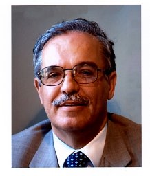 Franco Giannini合作论文数Dip . Ingegneria Elettronica;Università di Roma Tor Vergata;Monteluco di Roio;Monteluco di Roio, Università di Roma Tor Vergata4
 Fabio Vitobello合作论文数3Silvio Fenu合作论文数3
 Chiara Ramella合作论文数3
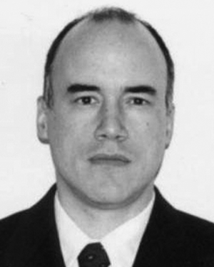 Franco Di Paolo合作论文数3e limiti合作论文数2
 Abbas Nasri合作论文数Dept Elect Engn, Univ Zanjan2Francesco Vitulli合作论文数2
 Andrea Bentini合作论文数2
 Suriani, A.合作论文数2Francois Deborgies合作论文数2
 Leonardo Pantoli合作论文数Department of Electrical and Information Engineering, University of L'Aquila2
 Giorgio Leuzzi合作论文数2f giannini合作论文数1Alessandro Barigelli合作论文数1Sven Boulanger合作论文数1Iolanda Ulisse合作论文数1
 Ruben Garvi合作论文数1
 Domenico Cannata合作论文数1
 Remy Morasso合作论文数1Matthias Schweikardt合作论文数1Marco Torrisi合作论文数1
 Alessandro Salvucci合作论文数1
 Giorgio Polli合作论文数1Dave McEwan合作论文数1
 Hans Ingelberts合作论文数1
 Adrian Pérez-Resa合作论文数1
 Ivan Ny Hanitra合作论文数Ecole Polytech Fed Lausanne, Integrated Syst Lab, Lausanne, Switzerland1
 Carmine Paolino合作论文数DET Politecn Torino, Corso Duca Abruzzi 24, I-10129 Turin, Italy1
 Steven Caicedo Mejillones合作论文数SIAE Microelettronica1
 Motahhareh Estebsari合作论文数Dept Elect & Telecommun, Politecn Torino1Valentina Lucaferri合作论文数Dept Engn, Univ Roma Tre1
 Francesca Criscuolo合作论文数Integrated Syst Lab, Ecole Polytech Fed Lausanne1
 Ayca Akkaya合作论文数1
 Elia Arturo Vallicelli合作论文数Sect Milano Bicocca, Natl Inst Nucl Phys1
 Alessandro Sitta合作论文数STMicroelectronics1
 Jordan Lee Gauci合作论文数Department of Microelectronics and Nanoelectronics, University of Malta1




