Ideal for advanced undergraduate and first-year graduate courses in analog filter design and signal processing, Design of Analog Filters integrates theory and practice in order to provide a modern and practical "how-to" approach to design. A complete revision of Mac E. Van Valkenburg's classic work, Analog Filter Design (1982), this text builds on the presentation and style of its predecessor, updating it to meet the needs of today's engineering students and practicing engineers. Reflecting recent developments in the field and emphasizing intuitive understanding, it provides students with an up-to-date introduction and design guidelines and also helps them to develop a "feel" for analog circuit behavior.Design of Analog Filters, Second Edition, moves beyond the elementary treatment of active filters built with opamps. The book discusses fundamental concepts; opamps; first- and second-order filters; second-order filters with arbitrary transmission zeros; filters with maximally flat magnitude, with equal ripple (Chebyshev) magnitude, and with inverse Chebyshev and Cauer response functions; frequency transformation; cascade designs; delay filters and delay equalization; sensitivity; LC ladder filters; ladder simulations by element replacement and by operational simulation; in addition, high-frequency filters based on transconductance-C concepts and on designs using spiral inductors are covered; as are switched-capacitor filters, and noise issues.Features: Includes a wealth of examples, all of which have been tested on simulators or in actual industrial use Uses the easy to learn program Electronics Workbench to help students simulate actual experimental behavior Provides sample design tables and design and performance curves Avoids sophisticated mathematics wherever possible in favor of algebraic or intuitive derivations Addresses practical and realistic designNew to this Edition: Includes a chapter on noise (Chapter 18) Chapter 16 offers a comparison of active and passive inductor design and a discussion of high-frequency active LC filter design using spiral inductors Texas Instruments OPA300 opamps replace the Harris HA2542-2 opamps
A transistor-only CMOS active-inductor with an all-NMOS signal path is presented. By tuning the varactor-augmented parasitic capacitance at the only internal node the circuit losses from submicron MOSFETs can be partially or fully compensated to permit realizing unlimited values of Q, with little frequency and no power-consumption penalties. Transistor-only second-order bandpass filters using the active inductor were built in the TSMC 0.18-μm CMOS process, and high filter Q was obtained by tuning the varactor. The highest center frequency measured was f 0 = 5.7 GHz for 0.2-μm gate lengths and the maximum repeatably measured Q was 665. Lower Qs can be obtained by reducing the capacitive compensation or by adjusting the circuit biasing. f 0 and Q are tunable via separate varactors. IIP 3 and input 1-dB compression point were simulated as 0.523 VPP and 0.128 VPP (−1.65 and −13.9 dBm from a 50-Ω source) at 5.7 GHz with Q = 100 and midband gain equal 4.7 dB. For the same conditions, the output noise and noise figure (R S = 50 kΩ) were simulated to be 0.8 μV/Hz1/2 and 25.6 dB, respectively. The filter core occupies an area of 26.6 μm × 30 μm and dissipates 4.4 mW at 5.4 GHz from a 1.8-V power supply. As the circuits use only MOSFETs they are fully compatible with standard digital CMOS processes. f 0 statistics were obtained by measuring 40 chips at identical biasing condition.
The design of a third-order elliptic low-pass LC ladder filter based on operational transconductance amplifiers (OTAs) which have good linearity over a large input range is presented. The design considerations are focused on high-frequency response, large signal-to-noise ratio, and notch depth, parameters which are all affected by parasitics. The filter is laid out with careful placement and routing to reduce parasitics, and is fabricated in 2-/spl mu/m CMOS technology through MOSIS. The measured results show that the cutoff frequency of the filter is 20 MHz, the signal-to-noise ratio is 70 dB, the notch depth is 60 dB, and the total harmonic distortion is less than 1% over a 2-V peak-to-peak input range.< >
In the paper an explicit, matrix description based procedure of generating canonical structures of low-pass elliptic filters with grounded and floating capacitors is given. A detailed comparison of third order leap-frog and inverse follow-the-leader structures is carried out. The major attention is focused on the sensitivity performance of the filters in question. Design guidelines that follow from the presented results are also given. It follows that filters containing floating capacitors can be viewed as an interesting alternative to the filters containing grounded capacitors only. Such filters exhibit good sensitivity performance, they have a smaller number of active elements and can be realized with all transconductances equal, which is important for integrated circuit implementations.
An all-transistor CMOS active inductor with a self-resonance frequency f/sub R/=5.7 GHz is presented. Large f/sub R/ is achieved by forming an all-NMOS signal path. The measured quality factor, Q, is as high as 665, but Q can be infinite theoretically. Both f/sub R/ and Q are tunable via biasing and on-chip varactors. As an example for using the active inductor, a high-Q bandpass filter for radio-frequency applications is designed. The inductor circuit was implemented in TSMC 0.18-/spl mu/m standard digital CMOS technology and occupies an area of 26.6 /spl mu/m/spl times/30 /spl mu/m including double guardrings. For a supply voltage of 1.8 V, the circuit consumes 4.4 mW, and IIP3 is measured at V/sub pp/=270 mV.
A general topology for transconductance‐capacitor ( G m ‐ C ) filters is presented that permits any continuous‐time analog G m ‐ C filter to be analysed via a matrix‐description. Based on these matrices, explicit formulas are derived for the transfer function and the sensitivities valid for any G m ‐ C filter topology. The approach leads to a useful relationship between the passive capacitor network of the filter and the degree of its transfer function. The matrix‐based approach is formulated especially for efficient use in computer‐aided analysis and design of Gm‐C filters, but ‘hand designs’ of G m ‐ C IFLF and LF filters are given as illustrative examples. A new, more general definition of G m ‐ C state‐space filters is proposed. Connections between the state matrices for voltage‐ and current‐mode state‐space G m ‐ C filters are formulated and two canonical transformations are defined that convert state‐space filters into direct state‐space ones, i.e. those having only grounded capacitors. Copyright © 2003 John Wiley & Sons, Ltd.
A linearization method based on the active-error feedback concept is presented for the design of highly linear, CMOS differential pair transconductor. The proposed circuit implementation combines a conventional source-coupled differential pair with a simple error amplifier in negative feedback path. As a result, improved linearity of the developed transconductor is obtained. SPICE simulations show that for 0.5/spl mu/m HP AMOS14TB process (MOSIS) with a /spl plusmn/2.5V power supply, total harmonic distortion (THD) at 1.2V/sub PP/ is less then 0.15% in comparison to 1.85% without linearization.
A high-frequency, low-voltage, low-power tunable oscillator using active inductors as resonators is designed and simulated in TSMC 0.20-/spl mu/m CMOS technology. The oscillation frequency of the small and compact transistor-only circuit is 4.95 GHz with THD/spl ap/-80 dB. Phase noise is approximately -81 dBc/Hz at 500-kHz offset. For a 1.8-V supply voltage, the power consumption is less than 1.16 mW.
A general approach for the analysis of continuous-time G(m)-C filters based on matrix descriptions is presented. Explicit formulas for the transfer function of any G(m)-C filter structure and for the sensitivity functions are derived. Relationships between the passive network of the filter and its transfer function are presented. The considerations lead to a new, more general definition of state-space G(m)-C filters. An example for the design of a G(m)-C filter with floating capacitors is given.
An all-transistor lowpass biquad based on an active inductor for operation up to several gigahertz is presented. A convenient parasitic notch near the passband edge sharpens the transition band. The filter can be tuned via biasing and on-chip varactors. Higher order filters can be constructed by simple direct cascading of the second-order blocks. A fifth-order filter example is designed and simulated in TSMC 0.18-/spl mu/m CMOS technology, with cutoff frequency at 4.57 GHz and passband ripple less than 1 dB.
The design of a very simple CMOS high-Q active inductor suitable for applications at low supply voltage and high frequencies is discussed. The inductor value, L, and the quality factor, Q, are independently adjustable by two PMOS varactors (variable capacitors). Alternatively, L can be tuned via a bias current. The inductor's DC level is set by a bias voltage. The self-resonance frequency, f/sub r/, is larger than 1GHz and very high values of Q, up to Q=/spl infin/, can be obtained so that circuit can be used for constructing high-frequency oscillators. The performance of the electronic inductor is demonstrated by simulation.
High-Q filter tuning based on envelope detection is discussed. The proposed tuning scheme is simple and can be used for high-frequency, high-Q filters. The circuit was designed using a 1.2 /spl mu/m CMOS process, with a 3 V single supply voltage. As a demonstration, a second-order bandpass section is used in the simulations, but the method can also be applied to lowpass and highpass second-order sections.
The magnitude and delay performance of integrated continuous-time inverse-follow-the-leader feedback (IFLF) and cascade lowpass filters are compared. The analysis is based on tenth-order filters with equiripple group delay, implemented in CMOS fully-differential form. Experimental and simulation results show that magnitude sensitivity in the passband of the cascade filter is larger than that of the IFLF filter. This result is as expected. The stopband and group delay performances, on the other hand, are worse in the IFLF filter than in the cascade filter
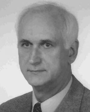 Stanislaw Szczepanski合作论文数Faculty of Electronics, Telecommunications and Informatics, Technical University of Gdansk15
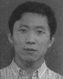 Haiqiao Xiao合作论文数7
 A WYSZYNSKI合作论文数7Wu, P.合作论文数5
 José Epifânio da Franca合作论文数Departamento de Engenharia Electrotécnica e de Computadores, Instituto Superior Técnico5
 Slawomir Marcin Koziel合作论文数Department of Engineering, School of Science and Engineering, Reykjavik University;Gdańsk University of Technology5R. Daasch合作论文数Electrical and Computer Engineering
Original Appointment5
Slawomir Marcin Koziel合作论文数Department of Engineering, School of Science and Engineering, Reykjavik University;Gdańsk University of Technology5R. Daasch合作论文数Electrical and Computer Engineering
Original Appointment5 Aydin I. Karsilayan合作论文数Department of Electrical and Computer Engineering;Texas A&M University4
 W. Robert Daasch合作论文数Electrical and Computer Engineering
Original Appointment3P VanHalen合作论文数2Latham, P.合作论文数2
W. Robert Daasch合作论文数Electrical and Computer Engineering
Original Appointment3P VanHalen合作论文数2Latham, P.合作论文数2 Kenneth R. Laker合作论文数Department of Electrical Engineering, University of Pennsylvania2
 Jacek Jakusz合作论文数2M. Wedlake合作论文数2CF CHIOU合作论文数1A. Wyszynski合作论文数1Chiang, D.H.合作论文数1Van Halen, P.合作论文数1
 Marek Andrzej Perkowski合作论文数Intelligent Robotics Laboratory, Department of Electrical and Computer Engineering, Portland State University1M. Ali Tan合作论文数1
 Bogdan Pankiewicz合作论文数Faculty of Electronics, Telecommunications and Informatics, Gdansk University of Technology1
 Branimir Pejcinovic合作论文数Portland State University1
 Michael A. Soderstrand合作论文数Synapse International, L.L.C.1m s ghausi合作论文数1Edmund Pierzchala合作论文数1




