This study aimed to investigate in a multicenter cohort study the radicality of colorectal cancer resections, to assess the oncosurgical quality of colorectal specimens, and to compare the performance between centers.
As CMOS devices continue to scale down in voltage and area, digital-based high-speed serial I/Os [1] become increasingly competitive with analog-based designs [2,3]. In addition to offering the PVT-independent performance of digital functions and superior power and area scaling to future technology nodes, digital-based I/Os can support advanced line modulation techniques that will become necessary as long-reach electrical channel data rates scale to 56Gb/s and beyond. The key enablers of a digital receiver are power and area efficient analog to digital conversion (ADC) and digital channel equalization. This paper describes the design of a 25Gb/s 2-level digital serial line receiver including a ¼-rate 5b flash ADC, an 8-tap feed-forward equalizer (FFE), an 8-tap decision-feedback equalizer (DFE), and a baud-rate clock and data recovery circuit (CDR). The receiver features a flash ADC, which employs a new power and area efficient slicer design capable of achieving high-precision (∼1mV) threshold accuracy with an associated on-chip calibration system. The 32nm SOI CMOS receiver achieves error-free operation with margin on a reflective transmission-line channel with 40dB half-baud loss.
This paper describes the implementation of a 4-level pulse-amplitude-modulation (4-PAM) receiver consisting of a 6-bit time-interleaved successive-approximation analog-to-digital converter (TI-SAR ADC), followed by a fully digital speculative 2-tap decision-feedback equalizer (DFE) operating at one-fourth of the modulation rate. The receiver, implemented in an experimental chip fabricated in 32 nm SOI CMOS, is designed to recover data at 56Gb/s over a channel with an attenuation of 11 dB at 14 GHz. The power consumption of the receiver is 202.7 mW at a supply of 1.2 V, achieving an overall energy efficiency of 3.62 pJ/b. The DFE along with area-optimized register arrays and memory-control buffers occupies an area of 0.154×0.169 mm 2 . Experimental results demonstrating a BER<;10 -8 are obtained using a (2 7 -1)-bit pseudo-random binary sequence (PRBS-7).
The Square Kilometre Array (SKA) is a future radio telescope, currently being designed by the worldwide radio-astronomy community. During the first of two construction phases, more than 250,000 antennas will be deployed, clustered in aperture-array stations. The antennas will generate 2.5 Pb/s of data, which needs to be processed in real time. For the processing stages from A/D conversion to central correlation, we propose an ASIC solution using only three chip architectures. The architecture is scalable - additional chips support additional antennas or beams - and versatile - it can relocate its receiver band within a range of a few MHz up to 4GHz. This flexibility makes it applicable to both SKA phases 1 and 2. The proposed chips implement an antenna and station processor for 289 antennas with a power consumption on the order of 600W and a correlator, including corner turn, for 911 stations on the order of 90 kW.
On-chip switched capacitor (SC) converters for multicore microprocessor power delivery have the potential to reduce the overall energy consumption of future multicore microprocessor systems by independently regulating the voltage supply of each core. This paper describes an on-chip SC converter that can be reconfigured between a 2:1 and a 3:2 voltage conversion ratio to support a wide output voltage range from a single input supply. Regarding SC converter analysis and modeling, this paper extends an existing state space model framework to include the flying capacitors' parasitic bottom plate capacitors, which for on-chip SC converters significantly influence both the capacitor currents and the converter efficiency. A reconfigurable SC converter that supports an output voltage range of 700 mV to 1150 mV from a 1.8 V input supply is implemented in a 32 nm SOI CMOS technology that features the high-density deep trench capacitor. The converter achieves a maximum efficiency of 85.2% at 2.1 W/mm(2) power density in the 2:1 configuration and a maximum efficiency of 84.1% at 3.2 W/mm(2) in the 3:2 configuration.
A 16 Gb/s receiver implemented in 22 nm SOI CMOS technology is reported. The analog frontend accepts a rail-to-rail input common-mode imposed from the transmitter side. It consists of a baseline wander compensated passive linear equalizer that AC-couples the received signal to the subsequent active CTLE with a regulated common-mode level. The programmable passive linear equalizer features a frequency response suitable for low-frequency equalization such as for skin-effect losses. When its zero is programmed at 200 MHz minimum frequency, the measured maximum mid-band peaking is 7 dB. The receiver architecture is half-rate and comprises an 8-tap DFE and a baud-rate CDR. With no FFE at the transmitter, 0.9 Vppd PRBS31 NRZ data are recovered error-free (BER<;10-12) across a copper channel with 34 dB attenuation at 8 GHz.
A 16 Gb/s I/O link receiver fabricated in 22 nm CMOS SOI technology is presented. Attenuation and ISI of transmitted NRZ data across PCB channels are equalized with a CTLE feeding an 8-tap DFE. The first tap uses digital speculation and the following seven taps are realized by means of the switched-capacitor technique. Timing recovery and control are performed with a Mueller-Müller type-A baud-rate CDR. The architecture is half-rate and requires one phase rotator. In total, each slice has six comparators to recover data and timing information. The secondorder digital CDR operates at quarter-rate and features a low-latency implementation of the proportional path. At 16 Gb/s, 1 Vppd PRBS31 data transmitted without FFE equalization is recovered across a PCB channel with 34 dB attenuation at 8 GHz. The measured tracking bandwidth is 31 kppm (16 GHz ± 496 MHz), and an amplitude of 3 UIPP is tolerated at 1 MHz sinusoidal jitter. The sinusoidal jitter amplitude tolerance measured at 10 Gb/s is 0.4 UIPP at 10 MHz and remains above 0.2 UIPP up to 1 GHz with PRBS31 data recovered (BER <; 10-12) across a PCB channel with 27 dB attenuation at 5 GHz. The power efficiency is 3.7 mW/Gb/s, including the full-rate clock receiver.
In this paper, we present a digital equalizer for 16Gb/s backplane I/Os which consumes only 3.5pJ/bit for an 8-tap FFE and 4+4 tap DFE operation. Several design choices were chosen to enable low power consumption at high speed. First, the FFE leverages parallelism to lower the supply voltage, while the DFE runs from a higher supply to close the feedback loop. Second, the FFE uses distributed arithmetic to reduce the number of required additions. Third, the DFE taps leave a window of four equalizer taps, which are covered by the FFE, in order to close the timing. Finally, a custom digital design style was chosen, which enabled the optimization of critical blocks and wires. At 0.6V supply, the FFE was measured to consume 1pJ/bit, while the DFE consumes 1.6pJ/bit at 0.9V while running at 16Gb/s.
The future trends in microprocessor supply current requirements represent a bottleneck for next generation high-performance microprocessors since the number of supply pins will constitute an increasingly larger fraction of the total number of package pins available. This leaves few pins available for signaling. On-chip power conversion is a means to overcome this limitation by increasing the input voltage - thereby reducing the input current - and performing the final power conversion on the chip itself. This paper details the design and implementation of on-chip switched capacitor converters in deep submicron technologies. High capacitance density deep trench capacitors with a low parasitic bottom plate capacitor ratio available in the technology facilitate high power density and efficiency in on-chip switched capacitor converter implementations. The measured performance of a 2 : 1 voltage conversion ratio on-chip switched capacitor converter implemented in 32nm SOI CMOS technology with 1.8V input voltage results in a power density of 4.6W/mm(2) at 86% efficiency when operated at a switching frequency of 100MHz.
Memory links use variable-impedance drivers, feed-forward equalization (FFE) [1], on-die termination (ODT) and slew-rate control to optimize the signal integrity (SI). An asymmetric DRAM link configuration exploits the availability of a fast CMOS technology on the memory controller side to implement powerful equalization, while keeping the circuit complexity on the DRAM side relatively simple. This paper proposes the use of Tomlinson Harashima precoding (THP) [2-4] in a memory controller as replacement of the afore-mentioned SI optimization techniques. THP is a transmitter equalization technique in which post-cursor inter-symbol interference (ISI) is cancelled by means of an infinite impulse response (IIR) filter with modulo-based amplitude limitation; similar to a decision feedback equalizer (DFE) on the receive side. However, in contrast to a DFE, THP does not suffer from error propagation.
The circuit presented is a power-efficient implementation of a 16 Gb/s I/O link NRZ receiver in 22 nm CMOS SOI. A CTLE feeds an 8-tap DFE for ISI equalization. The first tap uses digital speculation and the following seven taps are realized with switched-capacitor technique. Timing recovery and control are performed with a Mueller-Müller type-A baud rate CDR. The receiver architecture is half rate and requires only a single phase rotator. In total, six comparators in each even/odd signal path slice recover both data and timing information. The timing information extraction requires four additional comparators per slice in parallel to the two required by the first-tap DFE speculation. The CDR digital section operates at quarter rate and features a low-latency implementation for the timing control loop. At 16 Gb/s, 1 Vppd PRBS31 data transmitted without FFE equalization are recovered error-free (BER <; 10-12) across a PCB channel with 34 dB attenuation at 8 GHz. The measured tracking bandwidth is 30 kppm (16 GHz ±480 MHz), and an amplitude of 3 UIPP is tolerated at 1 MHz sinusoidal jitter. The sinusoidal jitter amplitude tolerance measured at 10 Gb/s is 0.4 UIPP at 10 MHz and remains above 0.2 UIPP up to 1 GHz with PRBS31 data recovered error-free (BER<; 10-12) across a PCB channel with 27 dB attenuation at 5 GHz. The power efficiency is 3.7 mW/Gb/s, including the full-rate clock receiver.
The signal integrity (SI) of double data rate (DDR) memory links is affected by signal reflections due to the multi-drop configuration of heavily loaded memory busses. Variable-impedance drivers, on-die termination (ODT), feed-forward equalization (FFE) and slew-rate (SR) control are typically implemented in DDR transmitters to address SI issues. In particular for multi-module, multi-rank configurations where speed throttling must be applied, SR control turns out to be most effective to combat reflections and crosstalk. Slewed signal edges reduce the spectral content above the bit rate frequency, whereas FFE dampens lower frequencies to compensate for channel loss, which may, however, be less of a problem at throttled data rates.
Tomlinson-Harashima (TH) precoding is a transmitter equalization technique in which the post-cursor intersymbol interference (ISI) is canceled by means of an infinite impulse response (IIR) filter with modulo (MOD)-based amplitude limitation. TH equalizers are suited for asymmetric links, such as DRAM interfaces, where the transmitter contains the equalization complexity and the receiver is kept simple. To increase the data rate, we propose the application of pipelining and half-rate operation to the ISI subtraction in the equalizer's feedback path. A TH equalizer with 8 taps, 6 bit resolution, and 2-PAM/4-PAM support has been implemented in 22-nm silicon-on-insulator (SOI) CMOS technology. In measurements, the feedback delay reduction techniques allow us to equalize 34-cm-long PCB traces having 12-dB loss with 7 × ISI reduction for 5.0-Gb/s 2-PAM signaling, and in 10.0-Gb/s 4-PAM mode completely closed eye diagrams are opened. The measured efficiency of the 145 μm× 115 μm transmitter is 1.2 pJ/bit in 4-PAM mode at 5.0 Gbaud with disabled equalization and increases linearly with 14 μW/Gbaud per 1% increase of the equalization tap weights.
 Thomas Toifl合作论文数Cisco Systems42
 Christian Menolfi合作论文数Cisco Systems42
 Marcel Kossel合作论文数IBM Research - Zurich40
 Thomas Morf合作论文数IBM Research – Zurich37
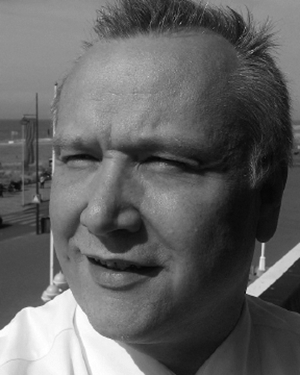 Martin L. Schmatz合作论文数IBM Zurich Research Laboratory28
 Peter Vettiger合作论文数IBM Zurich Research Laboratory19
 Jonas Weiss合作论文数17
 Matthias Braendli合作论文数IBM Zürich Research Laboratory16
 Pier Andrea Francese合作论文数IBM Zurich Research Laboratory16
 Lukas Kull合作论文数Cisco12
 David Webb合作论文数School of Engineering and Applied Science, Aston University;College of Engineering and Physical Sciences, Aston University;Aston Institute of Photonics Technology, Aston University11
 Toke Meyer Andersen合作论文数11g l bona合作论文数9o voegeli合作论文数9
 Michael Ruegg合作论文数9
 Robert Reutemann合作论文数9K. Datwyler合作论文数7Giuseppe Sasso合作论文数7h kaufmann合作论文数6
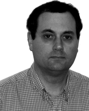 Troy J. Beukema合作论文数6
 Andreas Herkersdorf合作论文数School of Computation, Information and Technology, Technical University of Munich5Hans M Melchior合作论文数5H.-P. Dietrich合作论文数5Selim Dincler合作论文数5andreas moser合作论文数4
 Georg Guekos合作论文数Institute of Quantum Electronics, Department of Physics, ETH Zurich;Departement Informationstechnologie und Elektrotechnik, ETH Zurich4
 Michael P. Beakes合作论文数IBM T. J. Watson Research Center4M. K. Benedict合作论文数4
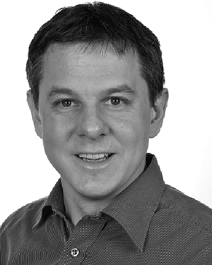 Florian Krismer合作论文数Power Electronic Systems Laboratory, Eidgenössische Technische Hochschule Zürich4
 Johann W. Kolar合作论文数Power Electronic Systems Laboratory, Department of Information Technology and Electrical Engineering, ETH Zurich4
 Rolf Clauberg合作论文数IBM Research Division, Zurich Research Laboratory4R. Grob合作论文数3Heinz Jaeckel合作论文数3David J Webb合作论文数3
 Lucas Bachmann合作论文数Epidemiology, Biostatistics and Prevention Institute, Universität Zürich;Medignition Inc.;Alleye;Augenmobil3Johann Steurer合作论文数3H. K. Seitz合作论文数3Rene Rüdlinger合作论文数3
 Sergey V. Rylov合作论文数ibm3P GUERET合作论文数2n cahoon合作论文数2W. Lemppenau合作论文数2kevin c gower合作论文数2robert j reese合作论文数2fritz gfeller合作论文数2michael r trombley合作论文数2George Von Bueren合作论文数2peter unger合作论文数2




